For a timber shear wall, nodal and line support types are needed to represent both shear connectors (anchor bolts) and hold-downs.
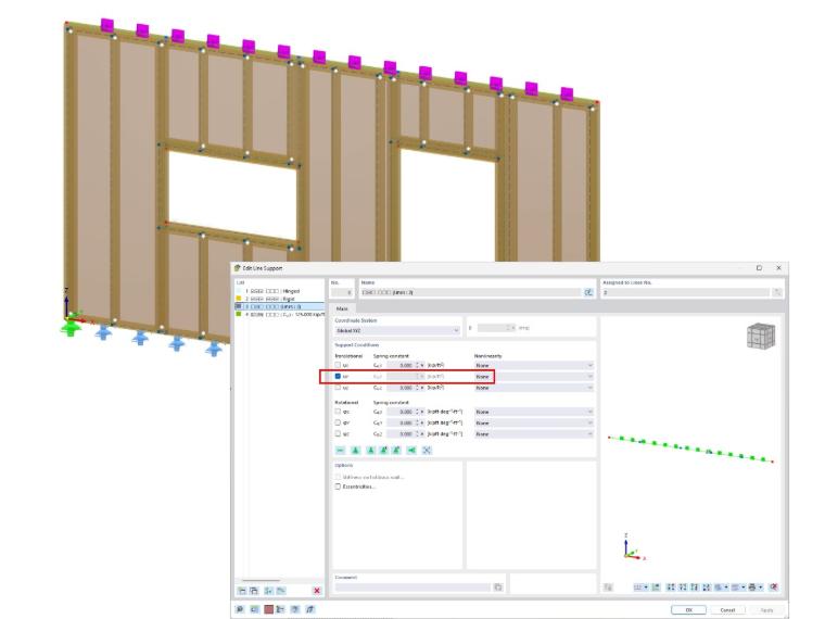
The first support is a nodal support applied only in the out-of-plane translation direction at the top of the wall. When modeling a full 3D model, these supports will not be needed if elements such as a floor are framing into the top of wall location.
When using the "beam panel" thickness type, it's suggested to apply the line support to the simplified beam panel surface line element or to the top/bottom plate member element and not the detailed sheathing surface line element.
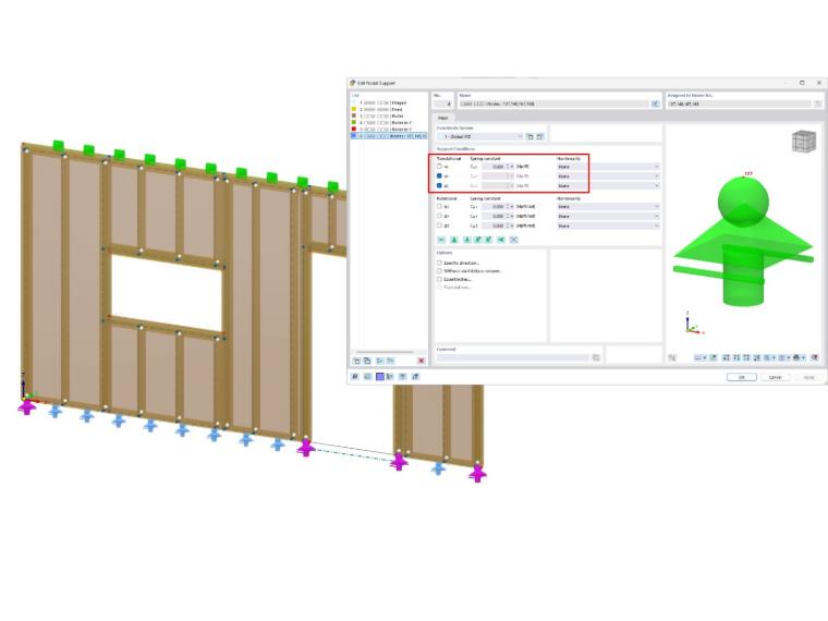
At the base of the wall, hold-downs are modeled as roller nodal supports. Translation is released along the length of the wall to freely allow movement in this direction. The nodal supports are typically applied to the base of the vertical stud at the relevant location.
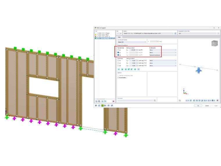
Lastly, pinned line supports are used at the base of the wall along the length to represent shear connectors. Translation along the length of the wall is not defined as a rigid support, but rather a spring constant to represent the shear connector stiffness.
The translation in the vertical direction is fixed but with a nonlinearity applied so that the support will fail in uplift. In the example model attached, this is set to "Failure if positive pZ".
As mentioned above when using the "beam panel" thickness type, it's suggested to apply the line support to the simplified beam panel surface line element rather than the detailed sheathing surface line element.
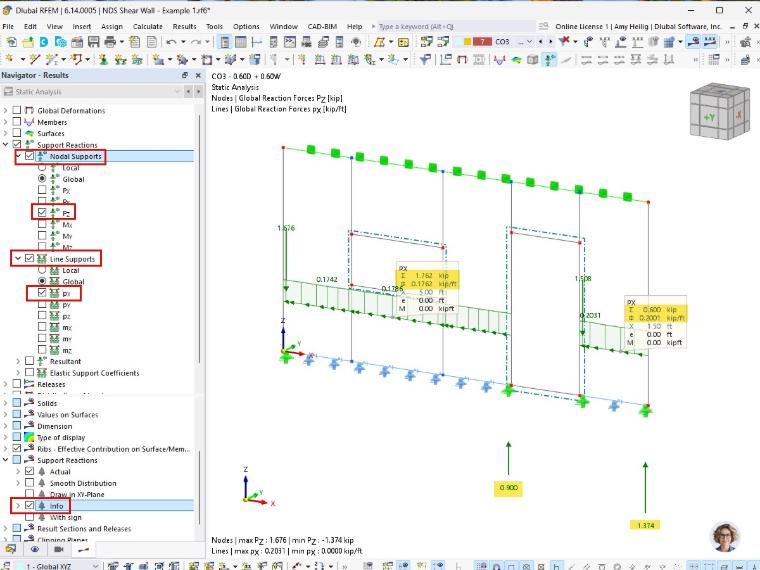
After running the static analysis calculation, the Support Reactions can be displayed graphically or as table results. When displaying graphically, either the Local or Global results can be viewed. The Local results are based on either the line or nodal support local axes, not the axes of the wall element. You can right-click on the support graphically to display the local axes.
The hold-downs are designed for the uplift/tension forces as shown at the nodal support locations. The shear connectors can be designed based on the summation force in the shear direction along the length of the wall.