


The following section explains the calculation method according to ACI 421.1R-20 [1] using a rectangular interior column as an example. The results of analytical formulas are shown and, finally, compared with the RFEM 6 results.
1. Formula According to ACI 421.1R-20 – Example of Inner Column
\(
J_x = d \sum\left[ \dfrac{l}{3} \cdot \left( y_i^2 + y_i y_{i+1} + y_{i+1}^2 \right) \right]
\)
\(
J_y = d \sum\left[ \dfrac{l}{3} \cdot \left( x_i^2 + x_i x_{i+1} + x_{i+1}^2 \right) \right]
\)
Structural system
The column cross-section and the effective depth of the slab are given for the calculation of the moments of inertia.
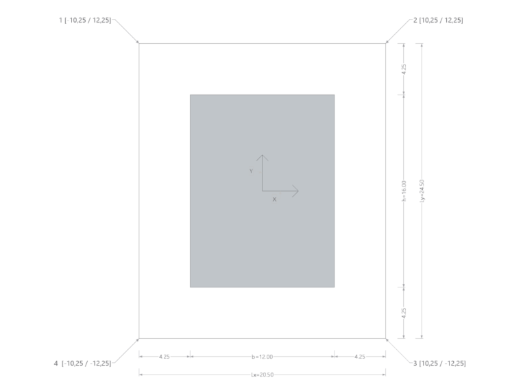
- Column cross-section: b = 12 in
- Column cross-section: h = 16 in
- Effective depth of the slab: d = 8.5 in
The control perimeter is located at a distance of 0.5d from the edges of the perimeter section. To calculate the moment of inertia, the distances from the corner points on the control perimeter to the center of mass of the control perimeter are required.
This results in the following coordinates for the corner nodes.
- Point 1 (-10.25 / 12.25)
- Point 2 (10.25 / 12.25)
- Point 3 (10.25 / -12.25)
- Point 4 (-10.25 / -12.25)
In the following example, the moments of inertia are calculated for illustrative purposes. The formula values yi and xi are the respective coordinates of Points 1 through 4.
The distances of each side are determined from the previously calculated distance coordinates.
- l1-2 = 20.5 in
- l2-3 = 24.5 in
- l3-4 = 20.5 in
- l4-1 = 24.5 in
Calculation of Moment of Inertia Ix:
Ix1 = d * [l1-2/3 * (y12 + y1 * y2 + y22)]
Ix1 = 8.5 * [20.5/3 * (12.252 + 12.25 * 12.25 + 12.252)]
Ix1 = 26148 in4
Ix2 = d * [l2-3/3 * (y22 + y2 * y3 + y32)]
Ix2 = 8.5 * [24.5/3 * (12.252 + 12.25 * -12.25 + (-12.25))2)]
Ix2 = 10417 in4
Ix3 = d * [l3-4/3 * (y32 + y3 * y4 + y42)]
Ix3 = 8.5 * [20.5/3 * ((-12.25)2 - 12.25 * -12.25 + (-12.25)2)]
Ix3 = 26148 in4
Ix4 = d * [l4-1/3 * (y42 + y4 * y1 + y12)]
Ix4 = 8.5 * [24.5/3 * ((-12.25)2 - 12.25 * 12.25 + 12.25)2)]
Ix4 = 10417 in4
∑ Ix = 73130 in4
Calculation of Moment of Inertia Iy:
Iy1 = d * [l1-2/3 * (x12 + x1 * x2 + x22)]
Iy1 = 8.5 * [20.5/3 * ((-10.25)2 - 10.25 * 10.25 + 10.25)2)]
Iy1 = 6102 in4
Iy2 = d * [l2-3/3 * (x22 + x2 * x3 + x32)]
Iy2 = 8.5 * [24.5/3 * (10.252 + 10.25 * 10.25 + 10.252)]
Iy2 = 21879 in4
Iy3 = d * [l3-4/3 * (x32 + x3 * x4 + x42)]
Iy3 = 8.5 * [20.5/3 * (10.252 + 10.25 * -10.25 + (-10.25)2)]
Iy3 = 6102 in4
Iy4 = d * [l4-1/3 * (x42 + x4 * x1 + x12)]
Iy4 = 8.5 * [24.5/3 * ((-10.25)2 - 10.25 * -10.25 + (-10.25)2)]
Iy4 = 21879 in4
∑ Iy = 55962 in4
2. Comparison with Analytical Formulas – Inner Column
- 2.1 – Formula from ACI 318-19 [2], page 108
\(
J_x = \dfrac{d(h + d)^3}{6} + \dfrac{d^3(h + d)}{6} + \dfrac{d(b + d)(h + d)^2}{2}
\)
\(
J_y = \dfrac{d(b + d)^3}{6} + \dfrac{d^3(b + d)}{6} + \dfrac{d(h + d)(b + d)^2}{2}
\)
b = 12 in
h = 16 in
d = 8.5 in
Ix = 75638 in4
Iy = 58061 in4
- 2.2 – Formula from Literature Jordahl [3] USA, Inc. | Studrails | 03-2023
\(
J_x = d \left( \dfrac{L_y^3 }{6} + \dfrac{L_x L_y^2}{2} \right)
\)
\(
J_y = d \left( \dfrac{L_x^3 }{6} + \dfrac{L_y L_x^2}{2} \right)
\)
b = 12 in
h = 16 in
d = 8.5 in
Lx = 20.5 in
Ly = 24.5 in
Ix = 73130 in4
Iy = 55963 in4
3. Comparison with Analytical Formulas – Edge Column
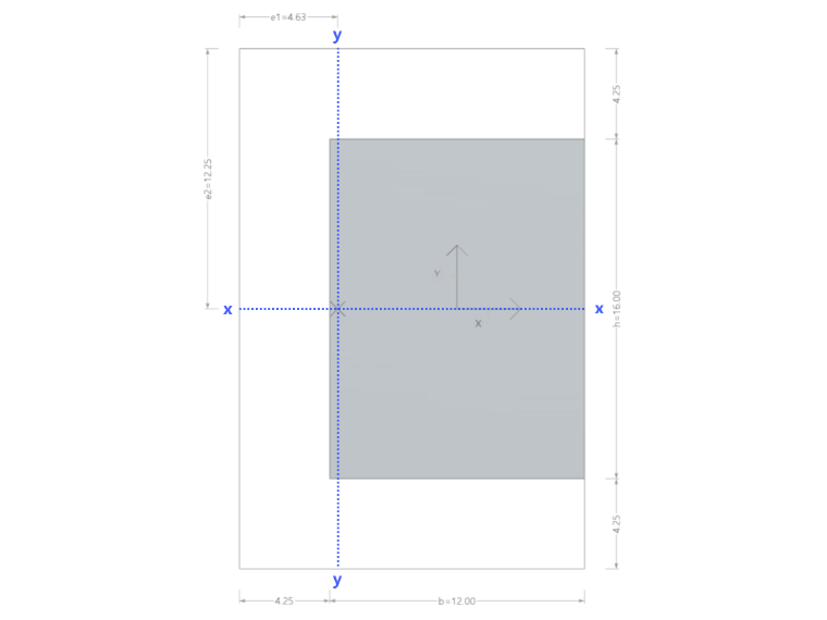
Due to their location at the edge of the slab, edge columns exhibit an asymmetry in their basic control perimeter. This shifts the center of gravity, and it is necessary to take it into account in subsequent calculations.
- 3.1 – Formula from CAC Concrete Design Handbook – 4th th Edition [4]
\(
J_x = \dfrac{(h + d)d^3 + (h + d)^3 d}{12} + 2\left(b + \dfrac{d}{2}\right)d(e_2)^2
\)
\(
J_y = \dfrac{(b + \dfrac{d}{2})d^3 + (b + \dfrac{d}{2})^3 d}{6} + \left(h + d\right) d(e_1)^2 + 2\left(b + \dfrac{d}{2}\right)d\left(\dfrac{b + \dfrac{d}{2}}{2 - e_1}\right)^2
\)
b = 12 in
h = 16 in
d = 8.5 in
e1 = (h + d/2)2 / (2h + b + 2d) = 4.63 in
e2 = (b + d)/ 2 = 12.25 in
Ix = 53125 in4
Iy = 15581 in4
Result Comparison
As already mentioned at the beginning of this technical article, the polar moment of inertia in RFEM 6 is calculated according to the approach specified in ACI 421.1R-20 [1]. Compared to manual calculations using the analytical formulas, the results are slightly lower; this is due to the neglect of a component of the moment of inertia (for rectangular geometries where b*d < sup > 3 < /sup >/6). Because of the lower moments of inertia, the results of the punching shear design are on the safe side. However, the real advantage of the implemented formula is its universal applicability; all cross-section shapes and geometric conditions can be taken into account.
| Punching Object Type | Chapter | Calculation Method | Manual Calculation [in4] | RFEM 6 [in4] | Deviation |
| Inner Column Ix | 1 | ACI 421.1R-20 | 73130 | 73130 | 0% |
| 2.1 | ACI 318-19 | 75638 | 73130 | 3.4% | |
| 2.2 | Jordahl Studrails | 73130 | 73130 | 0% | |
| Inner Column Iy | 1 | ACI 421.1R-20 | 55962 | 55963 | 0% |
| 2.1 | ACI 318-19 | 58061 | 55963 | 3.7% | |
| 2.2 | Jordahl Studrails | 55963 | 55963 | 0% | |
| Edge Column Ix | 3.1 | CAC Concrete Design Handbook | 53125 | 51871 | 2.4% |
| Edge Column Iy | 3.1 | CAC Concrete Design Handbook | 15581 | 13917 | 10.6% |