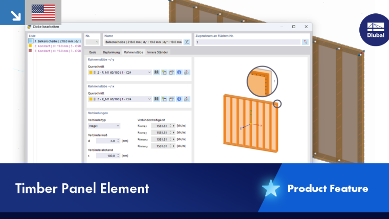
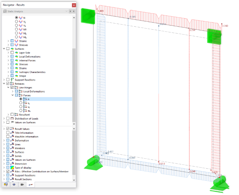
If you select the Beam panel thickness type, you can describe the properties of a timber panel wall or another supporting structure composed of members and surfaces in the dialog sections. Specific structures can be defined, if necessary, in further tabs. From the parameters of the elements (edge and inner ribs, sheathing, connectors), a member-surface thickness type is generated that also takes into account the elasticity of the fasteners.
Using the button
 at the bottom of the 'List', you can save the parameters of a beam panel as a template; the button
 allows you to import a user-defined beam panel.
Basis
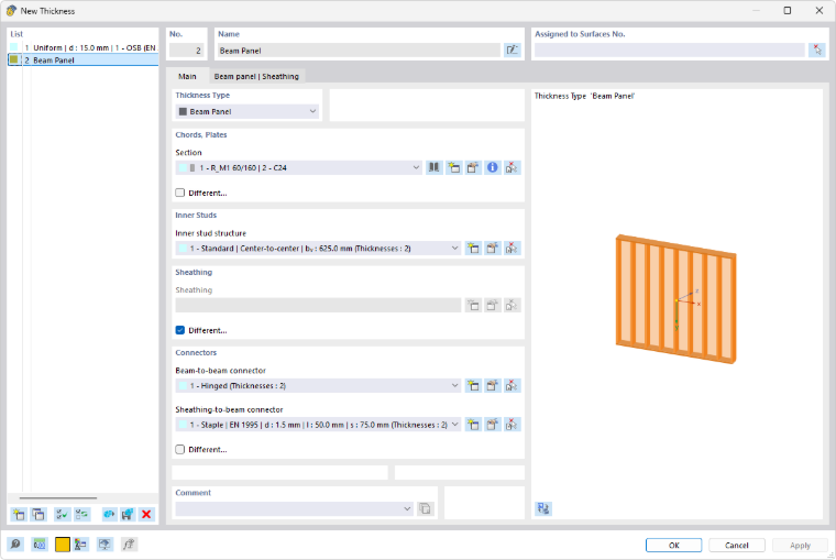
In the Basis tab, you define the general properties of the elements that make up the beam panel.
Edge ribs
Define the cross-section of the outer framing members. You can select this cross-section in the list or redefine it using the buttons
 and
and
 (see the chapter Cross-sections).
If the panel edges do not have a uniform cross-section, select the 'Different' check box. You can then assign the member cross-sections in the Beam panel | Beams tab.
Inner ribs
In the Inner ribs section of the Basis tab, you define the cross-section and spacing of the inner members. If no type has been defined for the inner ribs yet, click the button
. The 'New structure of inner ribs' dialog appears.
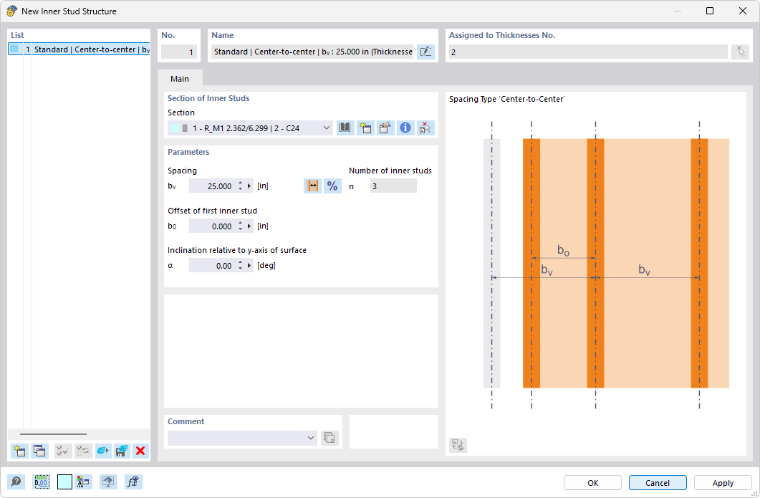
Select the 'Cross-section' in the list. Using the buttons
and
, you can define a new cross-section (see the chapter Cross-sections).
Then define the 'Spacing'. Using the button
 , you can control whether the spacing bv represents the overall spacing or the clear spacing (see the dialog graphic). The button
 allows you to switch the input from absolute values to relative spacings. The overall spacing and the clear spacing refer to the x-axis of the surface. The first position is assumed to be the point that is furthest away in the negative x-direction.
The 'Number of inner ribs' results from the geometry of the surface.
Sheathing
In the Sheathing section of the Basis tab, you define the properties of the panels. Since timber panels are usually sheathed on one side only, the 'Different' check box is selected by default. You can then assign the sheathing in the Beam panel | Sheathing tab for the front or back side. For a sheathing on both sides, deactivate the check box. Then click the button
to create a new type. The 'New sheathing' dialog appears.
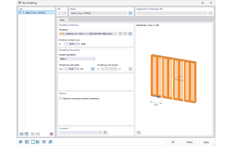
Define the 'Sheathing thickness' by selecting the appropriate entry from the list of thicknesses already defined. The button
provides the option of defining a new thickness with the corresponding material. OSB, gypsum, or hardboard materials are mostly suitable for timber sheathings. If required, you can apply a 'Rotation of input axes'.
In the 'Sheathing pattern' list, select the appropriate case of how the sheathing is arranged:
- Case 1: Full-area sheathing
- Case 2: Vertical sheathing strips with unit width wsu
- Case 3: Horizontal sheathing strips with unit height hsu
- Case 4: Staggered vertical sheathing strips with unit width wsu and unit height hsu
- Case 5: Staggered horizontal sheathing strips with unit width wsu and unit height hsu
- Case 6: Parallel vertical sheathing strips with unit width wsu and unit height hsu
The first position is assumed to be the point that is furthest away in the negative x-direction or the positive y-direction. If this is not the case, you can reverse the arrangement using the buttons
 or
or
 .
.
The 'Adjust to edge member centerlines' check box offers the option of arranging the slab edges in the center of the cross-sections of the edge ribs. The plate width is adjusted accordingly.
Connectors
In the Connectors section of the Basis tab, you define the properties of the connections that exist between the edge and inner ribs as well as between the sheathing and the inner ribs.
Rib-to-rib connector
The connection of the edge and inner ribs is set to hinged by default. To define a different connection type, click the button
. The 'New rib-to-rib connector' dialog appears.
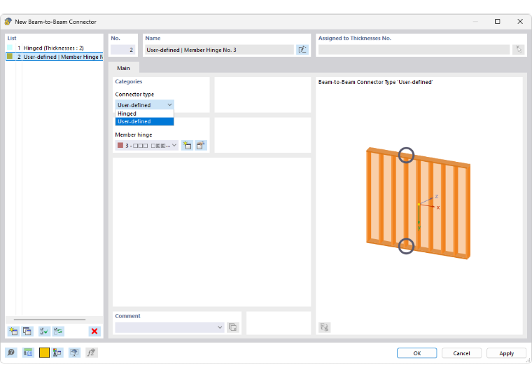
In the 'Connector type' list, two options are available for selection:
- Hinged: Member hinge about the y-axis and z-axis
- User-defined: Option for assigning a hinge type with user-defined degrees of freedom and stiffnesses (see the chapter Member hinges)
If there are no uniform hinge conditions for the rib connectors, select the 'Different' check box. You can then assign the connector types in the Beam panel | Connectors tab.
Sheathing-to-rib connector
If no type has been defined yet for the connection of the sheathing and inner ribs, click the button
. The 'New sheathing-to-rib connector' dialog appears.
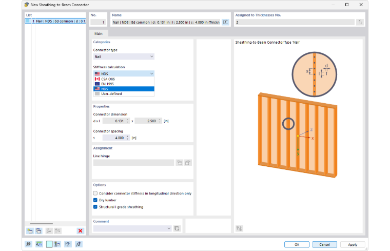
In this dialog, you define how the edge and inner ribs are connected to the sheathing. The following options are available in the 'Connector type' list:
- Nail
- Staple
- User-defined
For nails, you can select in a further list according to which standard the stiffness calculation is to be performed:
- EN 1995 (Table 7.1)
- CSA O86 (A.11.7)
- NDS (SDPWS Table C4.2.3D)
- User-defined
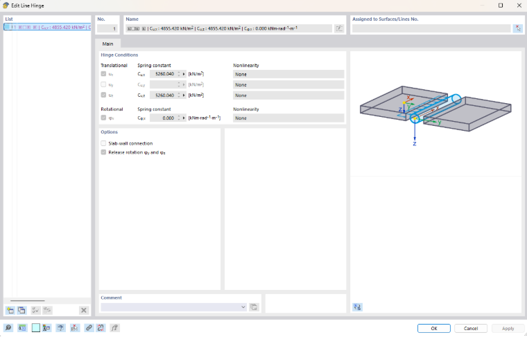
For nails and staples, you can specify the 'Connector dimension' (nail diameter or staple size) and the 'Connector spacing'. This determines the connector stiffnesses that apply to the respective sides and directions. The 'User-defined' option allows you to define both the parameters of the fastener and to assign a 'Line hinge' (see the chapter Line hinges). This allows you to model nonlinear slip curves, for example.
The stiffness from the fasteners is taken into account for each direction. If this does not correspond to the actual conditions, select the 'Consider connector stiffness only in longitudinal direction' check box.
If there are no uniform connectors on the edge and inner ribs, select the 'Different' check box. You can then assign the connector types in the Beam panel | Connectors tab.
Beam panel | Beams
If you have selected the Different check box in the Edge ribs section, you can define the cross-sections at the panel edges individually. Switch to the 'Beam panel | Beams' tab.
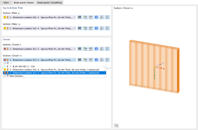
In the 'Top and bottom plate' section, you can assign the cross-sections that apply in the direction of the positive and negative y-surface axis – that is, the top and bottom framing profile.
In the 'Chords' section, you can assign the cross-sections that apply in the direction of the positive and negative x-surface axis (the "studs" at the panel edges).
Beam panel | Sheathing
In the Sheathing section, the Different check box is activated by default. In the 'Beam panel | Sheathing' tab, you can define whether the beam panel is sheathed on one or both sides and what the condition of the panels is in each case.
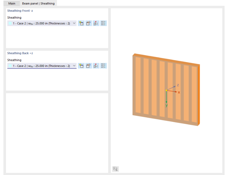
Select the sheathing(s) in the list. The 'Sheathing front -z' refers to the negative surface side (in the opposite direction of the local z-axis), the 'Sheathing rear +z' to the positive surface side. Clicking the button
 also sets the sheathing of one surface side for the opposite side.
Using the button
, you can define a further sheathing type in the New sheathing dialog.
Beam panel | Connectors
If you have selected the Different check box in the Connectors section, you can define the connections between the edge and inner ribs as well as between the sheathing and the inner ribs individually. Switch to the 'Beam panel | Connectors' tab.
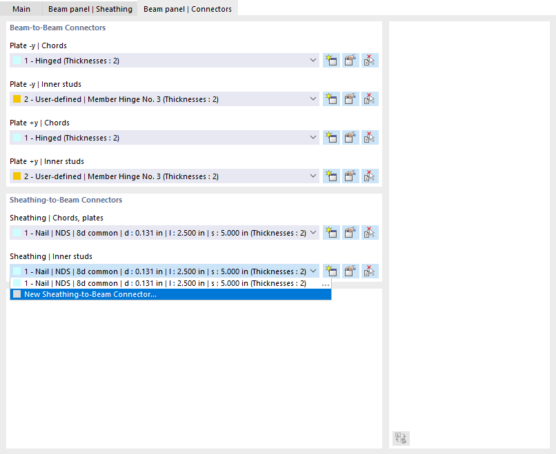
In the 'Rib-to-rib connector' section, you can assign the connection types that exist between the edge and inner ribs in the directions of the positive and negative y-surface axis – that is, between the top and bottom framing profile with the two framing studs, as well as between the top and bottom framing profile and the inner ribs.
Using the button
, you can define a further connector type in the New rib-to-rib connector dialog.
In the 'Sheathing-to-rib connector' section, you can assign the connection types that exist between the sheathing and the edge ribs as well as the inner ribs.
Converting generated surfaces and members into standard objects
If you assign the 'Beam panel' thickness type to a surface, the program generates surfaces and members with the corresponding geometry and stiffness properties from the parameters. These objects are marked in the Navigator – Data as generated objects in purple font and cannot be edited. If you want to edit the objects, the program offers a way to convert them into "real" surfaces and members. Proceed as follows:
- Double-click a generated surface or a generated member in the Navigator – Data.
- Click the button
 at the bottom of the object dialog.
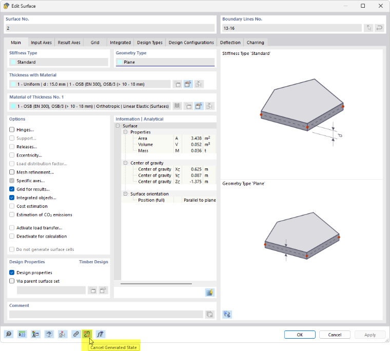
This function converts all generated objects of the beam panel into standard surfaces and standard members. The generated state is thereby dissolved and the generated objects are lost as such. Therefore, a corresponding warning appears before the function is executed.
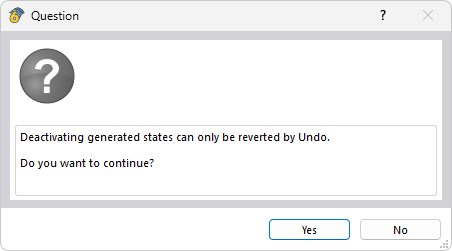
If you have used the function accidentally, you can restore the original state using the Undo button
 . Alternatively, you can close the file without saving.