


Analytical Model
This study adopts the design criteria specified in EN 1993-1-8 for evaluating bolt resistance (shear and tension) and plate resistance (bearing and punching shear), utilizing the limit state formulations provided in Table 3.4.
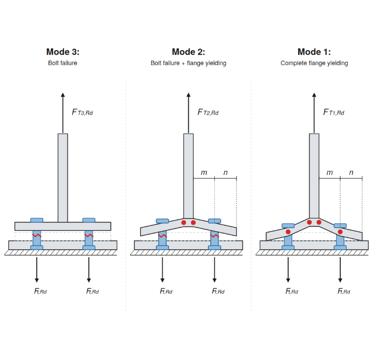
The design resistance of the equivalent T-stub is evaluated independently for the endplate and the column flange components. For each component, the governing design resistance, FT,Rd is defined as the minimum value derived from three potential failure mechanisms.
The individual resistance for each mode is calculated on the basis of the plastic moment capacity of the flange (Mpl,1,Rd and Mpl,2,Rd) and the tension resistance of the bolt group(∑Ft,Rd). These modes account for complete flange yielding (Mode 1), bolt failure coupled with flange yielding (Mode 2), and pure bolt fracture (Mode 3).
Failure Modes:
Plastic Resistance Moments:
Geometric Details of Beam-to-Column Connection
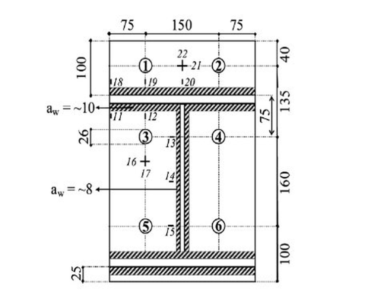
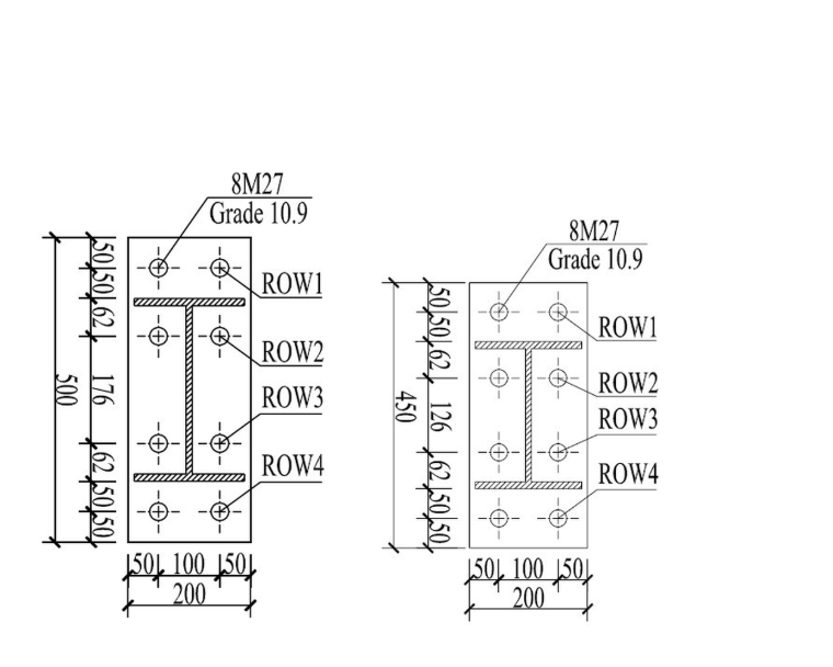
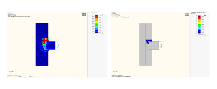
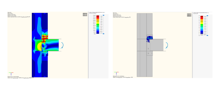
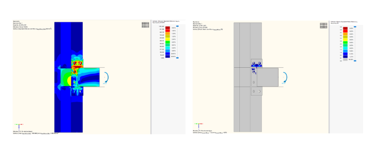
In line with standard construction practice, all beam and column members were fabricated from S355, Q690, and Q960 steel, whereas the endplates used the higher-strength Q690 and Q960 grades. The geometric configurations, including the end plate and bolt-group arrangements, are shown in Images 2 & 3 and the corresponding experimental test matrix.
Specimen JD1 (S355) used an HEM 300 column section. To assess the performance of a weak-column/strong-beam hierarchy, a uniform HEA 320 beam section together with 10 mm thick S690 end plates was retained. JD2 was fabricated from Q690 steel and JD3 from Q960 steel. The beam and column sections were H300×180×10×12 and H340×200×10×12 for JD2, and H250×180×10×12 and H300×200×10×12 for JD3. M24 grade 8.8 and M27 grade 10.9 bolts were used.
Discussion
Steel Joints for RFEM Solution
This study presents an experimental and numerical investigation into the structural performance of three extended high-strength steel end plate beam-to-column connections.
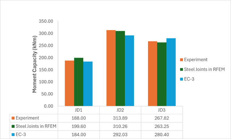
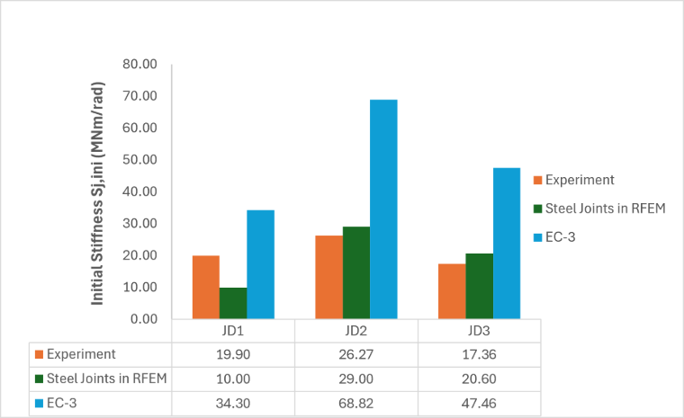
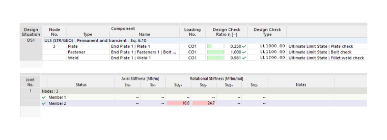
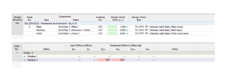
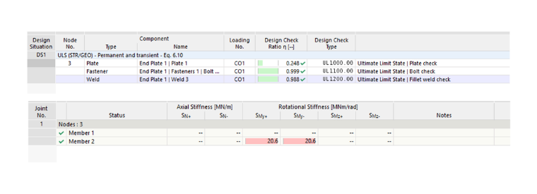
The experimental program was augmented by targeted T-stub characterization and high-fidelity finite element (FE) analysis. The connection design was fully integrated into the primary structural model using the FE-based Steel Joints add-on for RFEM 6. After validation against the experimental data and verification within the Eurocode 3 (EC3) framework, the FE models were employed to extract granular insight into localized deformation mechanics. Images 4 and 5 and Tables 1 and 2 present the comparison of moment resistance and stiffness across the experimental results, the Steel Joints add-on in RFEM, and EC3, while Table 3 summarizes the observed failure modes.
| Specimens | Experiment | Steel Joints in RFEM | EC3 | EC3/RFEM |
|---|---|---|---|---|
| JD1 | 188.00 | 199.60 | 184.00 | 0.92 |
| JD2 | 313.89 | 310.26 | 292.03 | 0.94 |
| JD3 | 267.82 | 263.25 | 280.40 | 1.07 |
| Specimens | Experiment | Steel Joints in RFEM | EC3 | EC3/RFEM |
|---|---|---|---|---|
| JD1 | 19.90 | 10.00 | 34.30 | 1.72 |
| JD2 | 26.27 | 29.00 | 68.82 | 2.37 |
| JD3 | 17.36 | 20.60 | 47.46 | 2.30 |
| Specimens | EC-3 | Steel Joints in RFEM | Experiment |
|---|---|---|---|
| JD1 | End plate and bolt | End plate and bolts row 1 & 2 | End plate and bolts row 1 & 2 |
| JD2 | End plate and bolt | End plate and bolts row 1 & 2 | End plate and bolts row 1 & 2 |
| JD3 | End plate and bolt | End plate and bolts row 1 & 2 | End plate and bolts row 1 & 2 |
Conclusions
Three bolted end plate joints (JD1–JD3) were studied by comparing experiments with the RFEM Steel Joints model and the EC3 hand calculation. For moment resistance, all three methods agreed well. RFEM matched the test results closely (within about 6%), and EC3 gave safe, slightly conservative values. EC3 can, therefore, be trusted for strength design.
The main difference was in initial stiffness. RFEM gave reasonable values, but EC3 greatly overestimated the stiffness of every joint — roughly 1.7 to 2.7 times the measured values. EC3 stiffness should, therefore, be used with care, especially in serviceability and deflection checks.
For failure modes, RFEM correctly predicted what was seen in the tests (end plate yielding with both bolt rows failing), while EC3 predicted a simpler single-bolt mode. In short, RFEM is a reliable tool for predicting joint resistance, stiffness, and failure, and can reduce the need for testing. EC3 is safe for strength but tends to overestimate stiffness.