With the default settings, the program displays the results of the envelope and the global directions X, Y, and Z that have a response spectrum assigned. These options are available at the top of the Navigator list (see the image Selecting Envelope or Direction ), so you can control the result display accordingly.
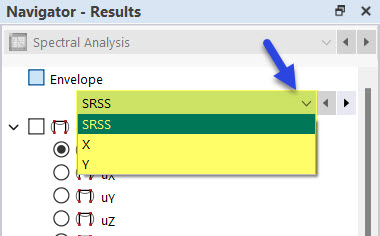
SRSS – Square Root of Sum of Squares
For a load case, the result designation specifies the type of envelope as follows:
| Description | Result Type |
|---|---|
| SRSS | Total envelope X, Y, Z |
| X | Envelope of all mode shapes in X |
| Y | Envelope of all mode shapes in Y |
| Z | Envelope of all mode shapes in Z |
| X, Mode Shape n | Envelope of the nth mode shape in X |
| Y, Mode Shape n | Envelope of the nth mode shape in Y |
| Z, Mode Shape n | Envelope of the nth mode shape in Z |
If you have specified in the Load Cases and Combinations dialog box that partial results for load cases or result combinations are to be output, these results are also available for selection for the load cases or the load cases used in the RC.
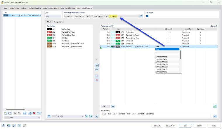
The result description comprises the load case number and the respective subresults. For Load Case 7 (LC7), for example, this is as follows:
| Description | Result Type |
|---|---|
| LC7.SRSS | Total envelope X, Y, Z |
| LC7.X | Envelope of all mode shapes in X |
| LC7.Y | Envelope of all mode shapes in Y |
| LC7.Z | Envelope of all mode shapes in Z |
| LC7.X, Mode Shape n | Envelope of the nth mode shape in X |
| LC7.Y, Mode Shape n | Envelope of the nth mode shape in Y |
| LC7.Z, Mode Shape n | Envelope of the nth mode shape in Z |
Scaled Sum (100% / 30% or 100% / 40%)
For a load case, the result designation specifies the type of envelope as follows:
| Description | Result Type |
|---|---|
| Scaled Sums | Total Envelope |
| X 100% ❘ Y 30% ❘ Z 30% | Factorized envelope of all mode shapes in X (100%), Y (30%), and Z (30%) |
| X 30% ❘ Y 100% ❘ Z 30% | Factorized envelope of all mode shapes in X (30%), Y (100%), and Z (30%) |
| X | Envelope of all mode shapes in X (100%) |
| Y | Envelope of all mode shapes in Y (100%) |
| Z | Envelope of all mode shapes in Z (100%) |
| X, Mode Shape n | Envelope of the nth mode shape in X |
| Y, Mode Shape n | Envelope of the nth mode shape in Y |
| Z, Mode Shape n | Envelope of the nth mode shape in Z |
For a result combination, the result description comprises the load case number and the respective subresults. For Load Case 7 (LC7), for example, this is as follows:
| Description | Result Type |
|---|---|
| LC7.Scaled Sums | Total envelope |
| LC7.SSX | Factorized envelope of all mode shapes in X (100%), Y (30%), and Z (30%) |
| LC7.SSY | Factorized envelope of all mode shapes in X (30%), Y (100%), and Z (30%) |
| LC7.SSZ | Factorized envelope of all mode shapes in X (30%), Y (30%), and Z (100%) |
| LC7.X | Envelope of all mode shapes in X (100%) |
| LC7.Y | Envelope of all mode shapes in Y (100%) |
| LC7.Z | Envelope of all mode shapes in Z (100%) |
| LC7.X, Mode Shape n | Envelope of the nth mode shape in X |
| LC7.Y, Mode Shape n | Envelope of the nth mode shape in Y |
| LC7.Z, Mode Shape n | Envelope of the nth mode shape in Z |
Absolute Sum
For a load case, the result designation specifies the type of envelope as follows:
| Description | Result Type |
|---|---|
| Absolute Sum | Total envelope X, Y, Z |
| X | Envelope of all mode shapes in X |
| Y | Envelope of all mode shapes in Y |
| Z | Envelope of all mode shapes in Z |
| X, Mode Shape n | Envelope of the nth mode shape in X |
| Y, Mode Shape n | Envelope of the nth mode shape in Y |
| Z, Mode Shape n | Envelope of the nth mode shape in Z |
For a result combination, the result description comprises the load case number and the respective subresults. For Load Case 7 (LC7), for example, this is as follows:
| Description | Result Type |
|---|---|
| LC7.AS | Total envelope |
| LC7.X | Envelope of all mode shapes in X |
| LC7.Y | Envelope of all mode shapes in Y |
| LC7.Z | Envelope of all mode shapes in Z |
| LC7.X, Mode Shape n | Envelope of the nth mode shape in X |
| LC7.Y, Mode Shape n | Envelope of the nth mode shape in Y |
| LC7.Z, Mode Shape n | Envelope of the nth mode shape in Z |
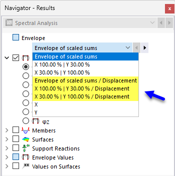
Subresults with “Displacement” Addition
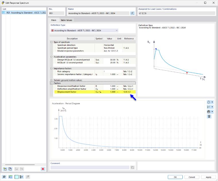
For a response spectrum with the Design Spectrum spectrum shape, a new set of subresults is generated that is linked to the selected rule for combination of directional components and is given the additional designation Displacement. The “Factors” category in the response spectrum dialog box (see the image Defining Displacement Behavior Factor) controls the displacement factor used to scale the subresults and generate them as additional results called “Displacement.”
The definition of the displacement factor varies depending on the standard selected for the “Dynamic Analysis” add-on. In the Response Spectrum dialog box, the “Reference” column specifies the section in which the displacement behavior factor is defined. It is recommended to consult this section of the standard to gain a better understanding of the calculation of seismic displacement.