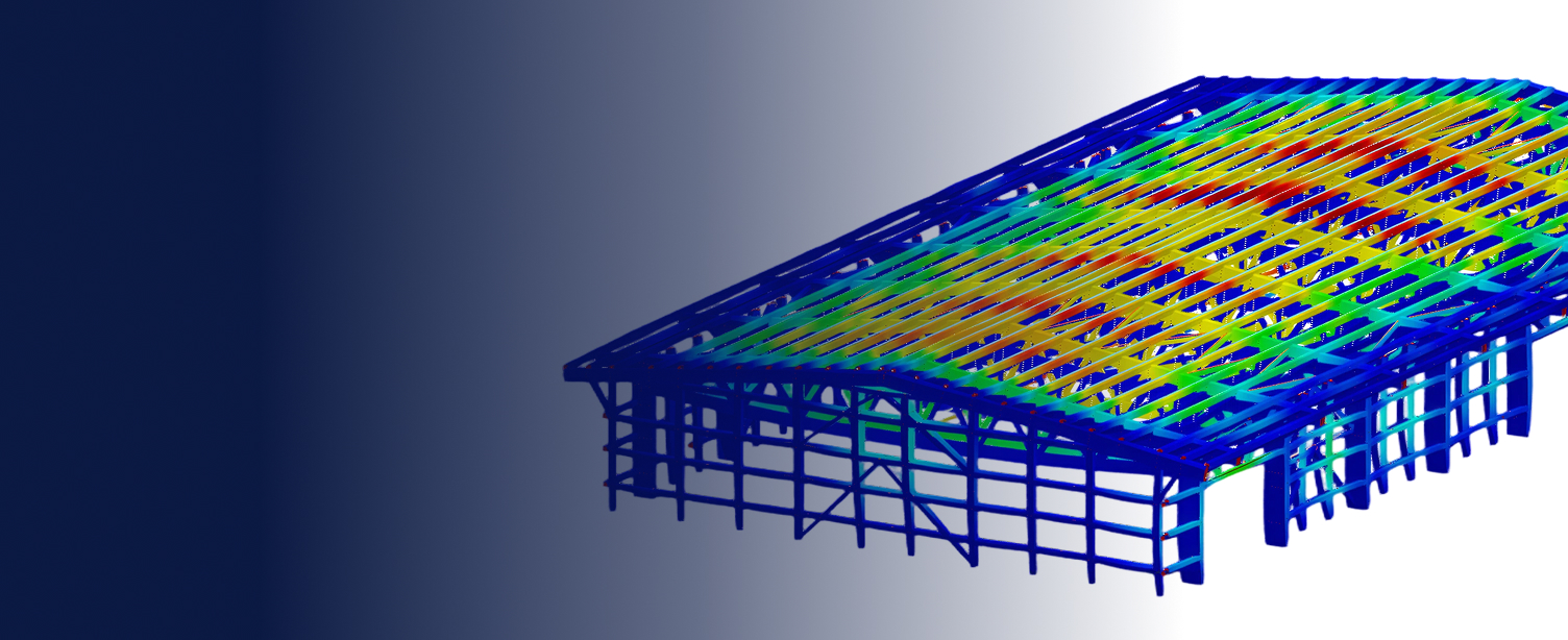
Designing a 28-Meter Timber Frame Down to the Critical Nodes
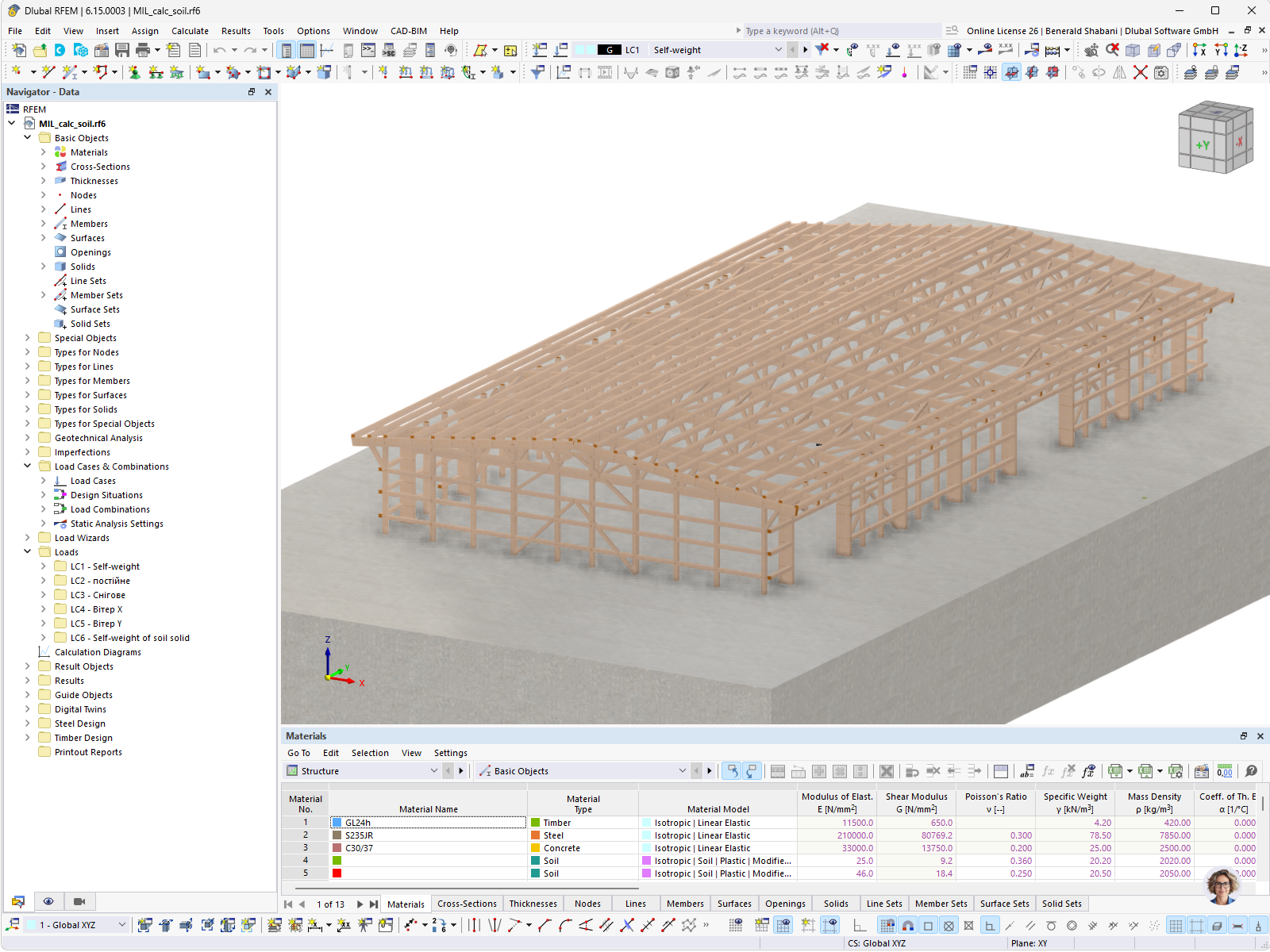
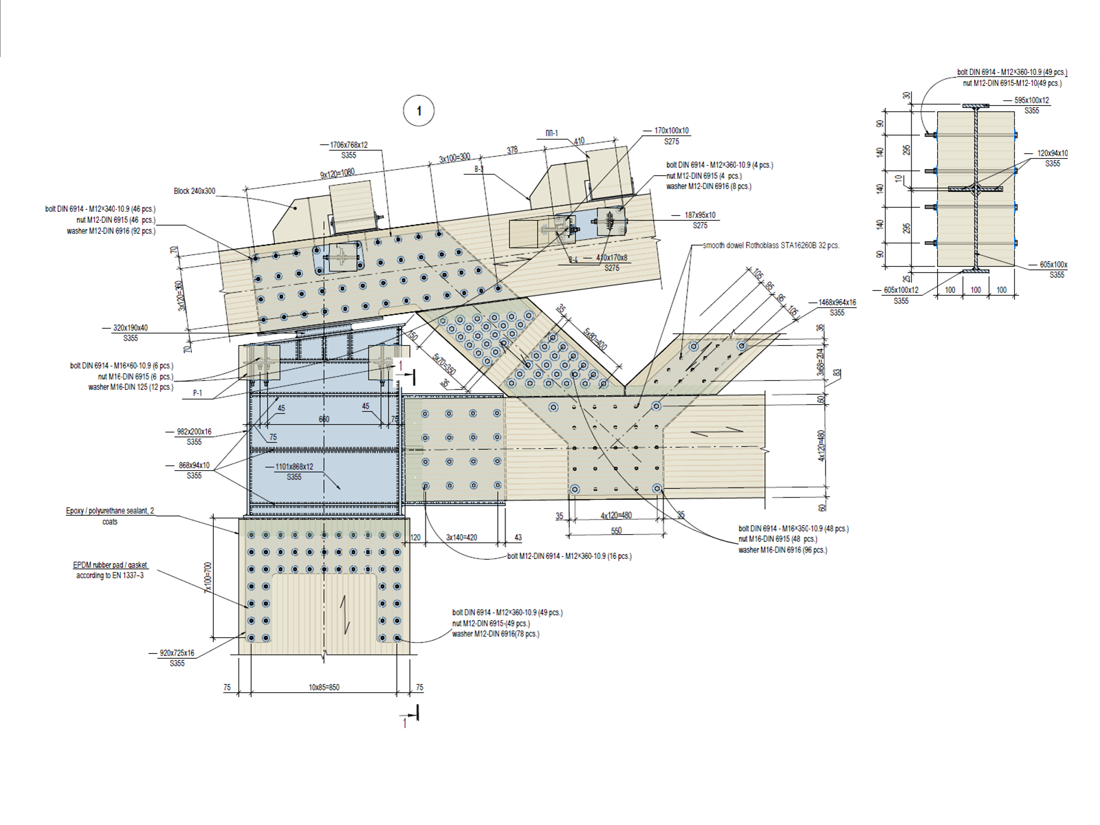
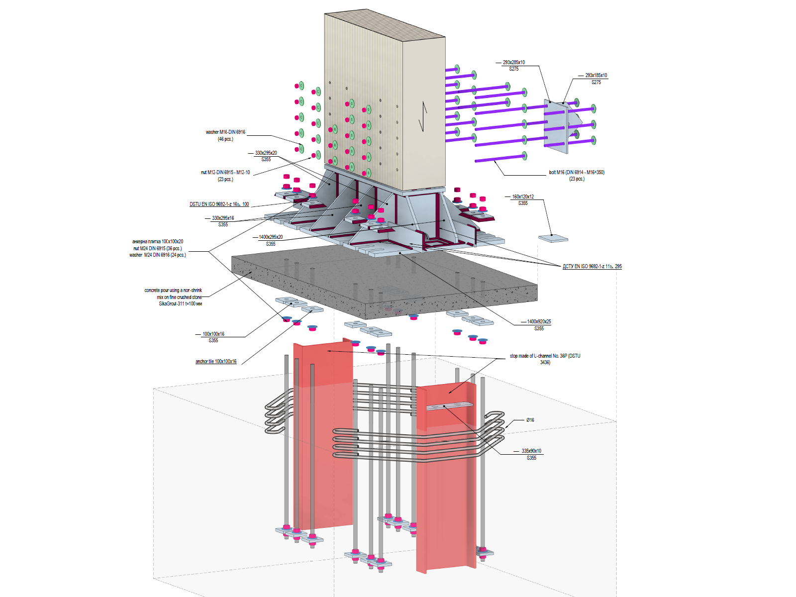
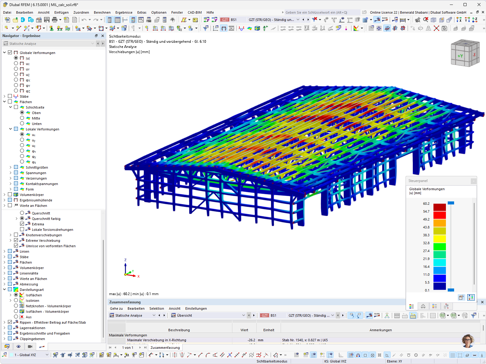
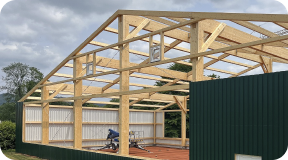
The production hall had to span 28.0 m with a frame spacing of 7.2 m to accommodate large woodworking machines, all supported by glued-laminated timber columns and truss-like roof girders. The real difficulty lay in the highly stressed eaves (support) connections: verifying both the overall stability of the long-span structure and the local stress state at these critical nodes is very hard to do reliably with simplified hand calculations. The design also had to account for the cast-in-place single foundations and the supporting soil, so the load path from roof to ground needed to be captured in one consistent analysis that the reviewing authorities could trust.
One FE Model from Roof Girder to Subsoil
RFEM allowed Dmytro Matiushchenko to build the entire hall as a single finite element model, accurately representing the long-span truss elements and the demanding eaves connections while running code-based verification according to Eurocode 5. The flexibility of the FE model made it possible to combine the glued-laminated timber frame, the reinforced concrete foundations, and the subsoil in one environment: the single foundations were modeled in cast-in-place concrete, and the soil was represented with the Geotechnical Analysis add-on. With the timber, steel, and geotechnical add-ons working on the same model, both the global stability and the local stress state at the critical nodes could be checked with confidence, something that would otherwise be very difficult to achieve reliably.
Advantages of Using Dlubal Software
- Flexible FE modeling for complex timber geometry – curved glulam frames, truss girders, and CLT panels can be modeled freely while still receiving reliable Eurocode 5 verification.
- True hybrid modeling in one file – timber, steel, and reinforced concrete are combined in a single model, with the subsoil added through the Geotechnical Analysis add-on.
- Automatic cross-section optimization – the timber design add-on optimizes sections automatically, saving significant time on long-span members.
- Ready-to-use reports – high-quality, informative output that requires no additional rework by the structural engineer before submission.