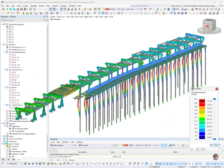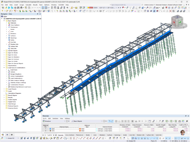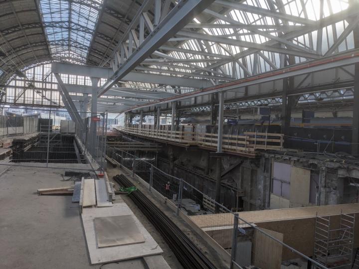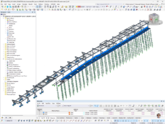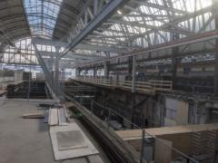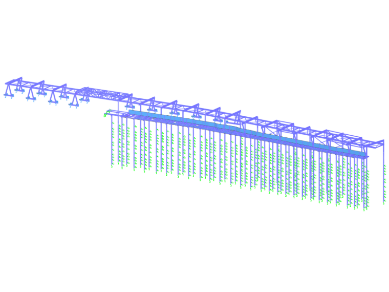
The craneway essentially consists of two continuous longitudinal beams made of HEB 550 steel sections with a total length of approximately 200 m. The longitudinal beams are generally supported at intervals of about 12 m (39.4 ft) by steel frames made of HEB 700 sections. Depending on their location, the frames are founded either on the existing station structure or on newly constructed piles. Horizontal stiffening is provided by rigid frame joint connections. To facilitate the future reuse of the structure and simplify assembly, the number of welded connections was reduced to a minimum.
A comprehensive finite element model was created in RFEM 6 for the craneway analysis. Various crane positions as well as different wind load cases and temperature effects were taken into account. Since part of the craneway is located beneath the station roof, while other areas are exposed to the elements, different wind and temperature conditions were applied to the respective areas.
Furthermore, three different soil stiffness scenarios were analyzed. This allowed to determine the influence of different horizontal pile stiffnesses on the structural behavior and the resulting deformations of the craneway.
Based on the large total length of the structure, several frames with sliding supports were created. They enable the craneway to absorb temperature-induced axial strains and thereby eliminate excessive constraint forces resulting from the temperature changes.
| Location | 1012 AA Amsterdam, Netherlands |
| Investor | Strukton PHS Rail Civiel BV |
| Object Monitoring | Anteagroup BV |
| Steel Manufacturer | Qumey Metaalindustrie B.V. Broeze Nijverdal |
| Structural Design | A&I Kwant Civiel B.V. |