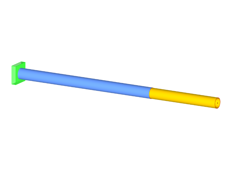
A member hinge limits the internal forces that are transferred from one member to other members. Hinges can only be arranged at the member ends, not at locations along the member.
Some member types are already equipped with hinges: a truss member, for example, does not transfer any moments, and a cable member transfers neither moments nor shear forces. You cannot assign hinges to such member types. The input is locked.
Basic
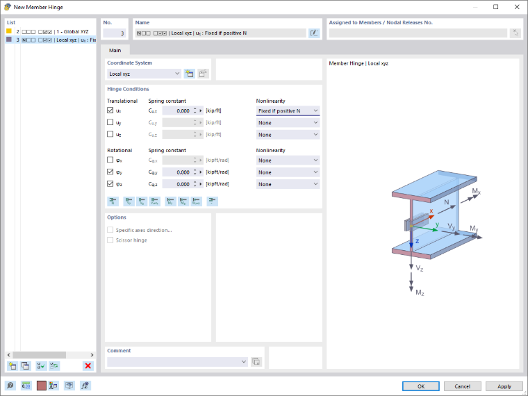
The Basic tab manages elementary hinge parameters.
Coordinate System
A member hinge can be related to one of the following axis systems:
- Local member axis system x,y,z
- Global coordinate system X,Y,Z (optionally as scissor hinge)
- User-defined axis system U,V,W
As a rule, the hinges are related to the local member axis system. Scissor hinges (see image Member crossing), however, are only possible in the global or a user-defined axis system.
- banner.tip
- banner.text
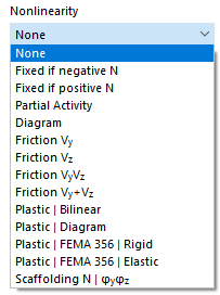
Fixed if internal force negative or positive
This allows you to easily control whether only positive or negative forces or moments are transferred at the member end. A ux hinge with the nonlinearity 'Fixed if N positive', for example, means that tensile forces (positive) but no compressive forces (negative) are transferred at the member end. For negative axial forces, a hinge is thus effective.
In the case of a local coordinate system, the internal forces are related to the local xyz member axis system.
If you select a different nonlinearity, you can define the parameters in the Partial activity, Diagram, Friction, or Scaffolding diagram tabs.
Options
The 'Scissor hinge' is available in the global or user-defined coordinate system. This allows you to model the crossing of continuous members.
Example
Four members are connected at a node. The members transfer moments in their "continuation direction," but not to the other pair of members. Only axial and shear forces are transferred at the node.
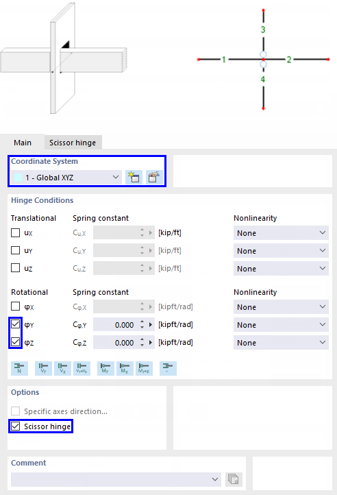
Assign the hinge either to members 3 and 4 or to members 1 and 2. The other crossing pair of members is not assigned a hinge.
Partial Activity
The Partial activity of a hinge component is available as a nonlinear property of the member hinge (see image Selecting hinge nonlinearity).
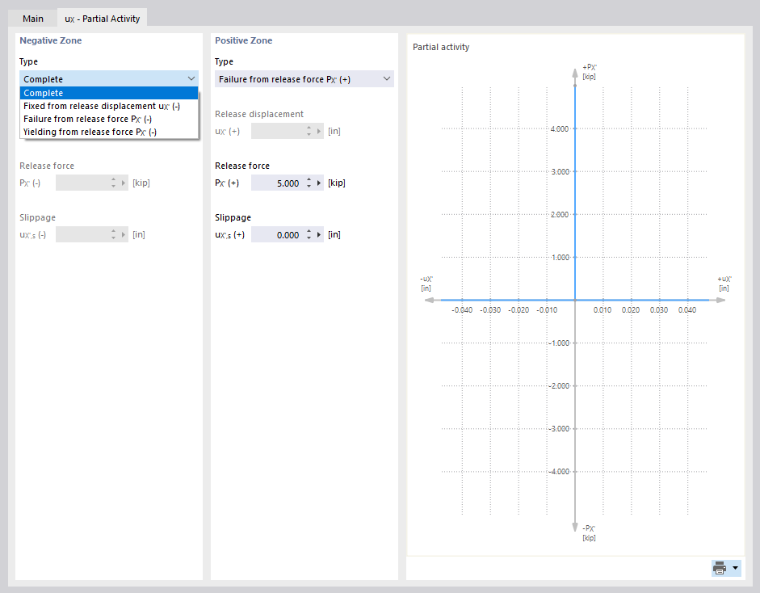
Define the activity of the hinge for the 'Negative zone' as well as for the 'Positive zone'. In the 'Type' list, various criteria are available for selecting the effectiveness of the hinge.
- Complete: The displacement or rotation is fully possible through the hinge.
- Fixed from release displacement/release rotation: The hinge is only effective up to a certain displacement or rotation. If exceeded, a rigid connection or restraint becomes effective.
- Cracking from release force/release moment: The hinge is only effective up to a certain force or moment. If exceeded, the hinge fails and no longer transfers the internal force.
- Yielding from release force/release moment: The hinge is only effective up to a certain force or moment. If exceeded, the strains increase, but the internal force no longer does.
- Spring failure: For a hinge with spring stiffness, the component of the hinge is not effective.
Most hinge types can be combined with a 'Slippage', whereby the hinge only becomes effective after a certain displacement or rotation.
Diagram
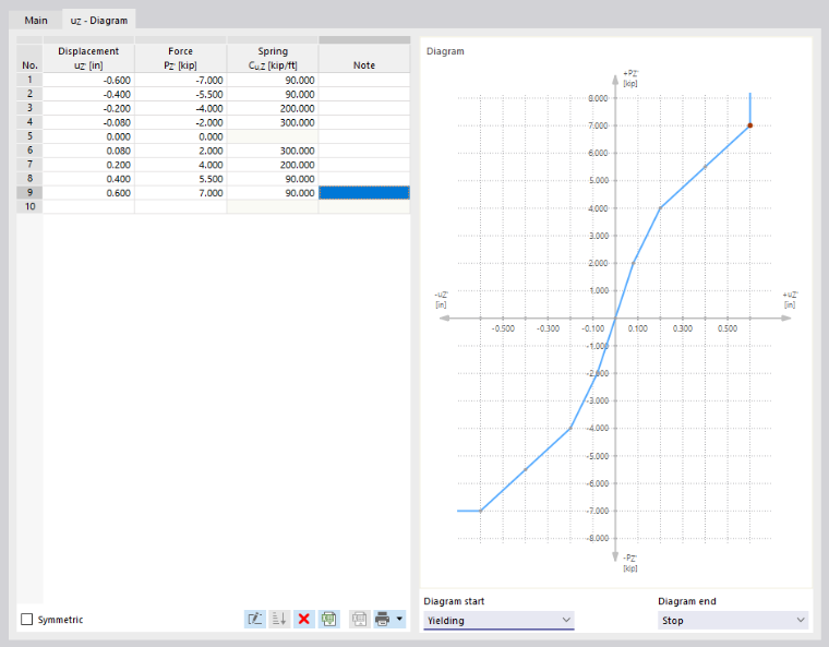
The Diagram of a hinge component is available as a nonlinear property of the hinge (see image Selecting hinge nonlinearity).
- banner.text
Friction
In the 'Nonlinearity' list, four options are available for defining the friction of a translational hinge as a function of another hinge component (see image Selecting hinge nonlinearity).
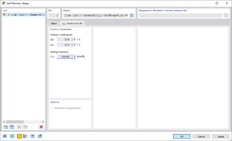
The transferred hinge forces are set in relation to the axial or shear forces acting in another direction. Depending on the selection in the 'Basic' tab, the friction depends on only one or on two internal forces. The following relationship exists between the hinge friction force and the axial force or shear force:
Plastic
Plastic hinge properties are important for pushover analyses. For the Plastic option of a nonlinear hinge component, four options are available (see image Selecting hinge nonlinearity):
- Bilinear
- Diagram
- FEMA 356 | Rigid
- FEMA 356 | Elastic
- banner.text
Scaffolding Diagram
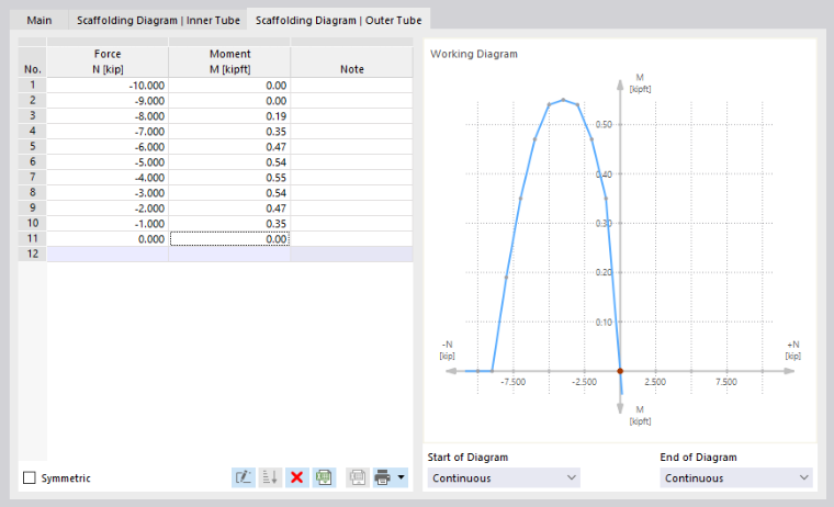
The Scaffolding diagram of a hinge component is available as a nonlinear property of the hinge (see image Selecting hinge nonlinearity). This allows you to model the mechanical effect of a plugged tube connection with an inner tube stub between two members. The substitute model transfers – depending on the compressive state at the member end – the bending moment via the pressed outer tube and, due to positive locking, additionally via the inner tube stub.
You can describe the hinge properties separately in the 'Scaffolding diagram | Inner tube' and 'Scaffolding diagram | Outer tube' tabs.
- banner.text@For the nonlinearity type 'Scaffolding | Nφyφz', the translational component ux is coupled with the rotational components φy and φz.
- /
The options presented in the Diagram section are available for defining the parameters.