


Opening Global Settings
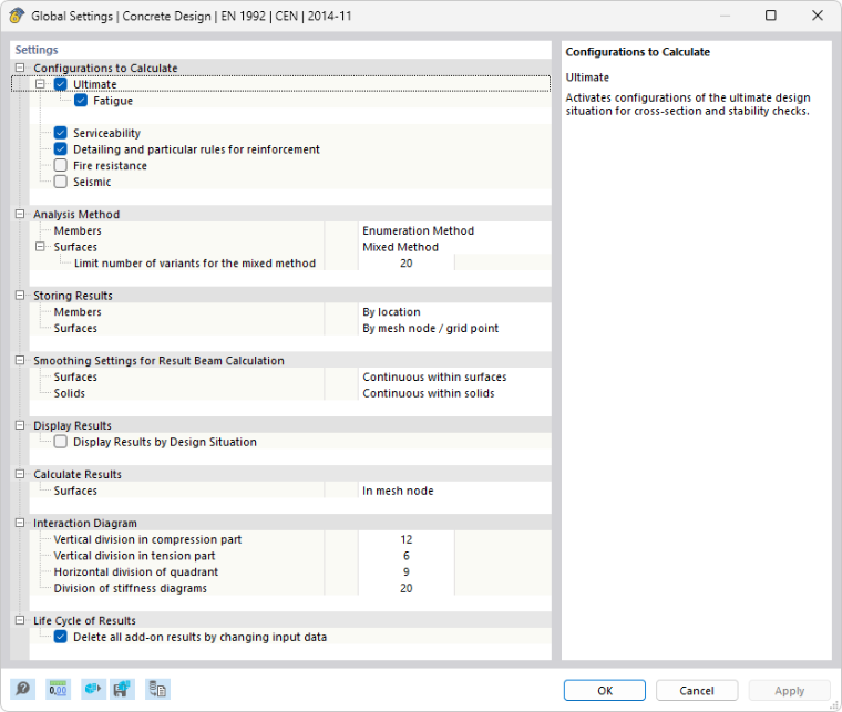
Basic settings for concrete design are managed in the “Global Settings” dialog box. This dialog box is essentially independent of the standard you have selected in the model base data. However, the default values may differ.
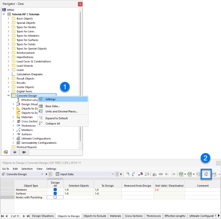
You can access the global settings using one of the following methods:
- Shortcut menu in the “Concrete Design” navigator entry
- Button
 in the toolbar of the concrete design tables
Global Settings
Use the
 button to restore the default settings for the standard.
Configurations to Calculate
Use the check boxes to specify which design configurations should be analyzed generally. For design according to EN 1992‑1‑1, the "Ultimate" and "Serviceability" configurations are activated by default.
Analysis Method
The "Enumeration Method" is set for both members and surfaces by default. The "Envelope Method" and the "Mixed Method" are available as further design methods.

- Enumeration Method: All load combinations in a design situation are calculated individually, one by one. This usually leads to the most accurate results, but may also lead to increased calculation time.
- Envelope Method: The enveloping internal forces are calculated first, which result from the extreme values for the design situations. The envelope is then used for the design. This usually leads to a shorter calculation time, but in certain circumstances, it may lead to an inefficient design compared to the Enumeration Method.
- Mixed Method: Both methods described above are combined here. There is the option to adjust "number of variants" as a limit value, where you can switch between the Enumeration Method and the Envelope Method. With the default value of 20, the program uses the Enumeration Method as long as the number of "result variants" is less than 20. If the number of variants in a design situation is greater than or equal to 20, the Envelope Method is used to save calculation time. You can make the settings separately for members and surfaces.
Optimization – Maximum Allowable Design Ratio (in Preparation)
The design concept is based on a design procedure. This means that you specify a cross-section and a reinforcement, and the program carries out the design checks with these specifications. In the future development of RFEM and RSTAB, the optimization of cross-sections and reinforcement specifications is also planned. A specific design criterion or a percentage of utilization is sought for for the individual design checks. You can also specify a value deviating from "1.00", which may be smaller or larger, in order to influence the optimization goal.
Storing Results
You can specify whether to save the results for the individual x-locations of a member ("By location") or for the member as a whole only ("By object"). The latter takes less time, but makes a detailed evaluation in the result tables more difficult.
For surfaces, you can specify whether to save the results for each FE mesh node or grid point and each design ("By location"), or whether to save only the result of the governing point in the surface for each design ("By object").
Smoothing Settings for Result Beam Calculation
A result beam integrates the internal forces of members, surfaces, or solids. For the design in the add-on, you can control which smoothing setting is applied when integrating the results. The list offers the following options:
- Constant on mesh elements
- Non-continuous
- Continuous within surfaces/solids (default)
- Continuous within surface sets/solid sets, otherwise within surfaces/solids
- Continuous within all surfaces/solids
The individual options are described in the chapter Result Smoothing of the RFEM manual.
Display Results
This check box controls whether the design results are displayed for each design situation. It is deactivated by default so that you can work in the result tables without long waiting times.
Calculate Results
This option controls whether the locations of the FE mesh nodes or the grid points should be used for the design of the surfaces (see the chapter Results by Surface of the RFEM manual).

This setting affects the results that are displayed in the Concrete Design result tables and in the design details. This has no influence on the graphic results.
The two options in the list affect the results in the tables and in the design check details: They allow you to control whether the values of the mesh nodes or the grid points are displayed. The surface grid represents an output independent of the FE mesh, consisting of result points at regular intervals (see the chapter Surfaces of the RFEM manual). These options do not affect the graphical display.
Interaction Diagram
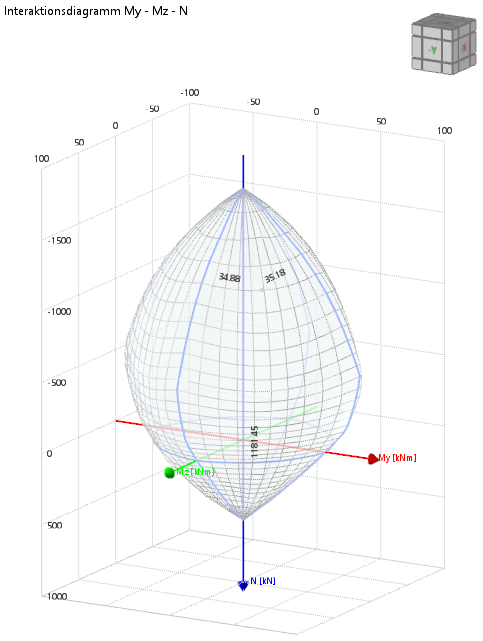
Here, you can specify the parameters that should be used for the result display of the design details as an interaction diagram.
Life Cycle of Results
The Concrete Design results are deleted as soon as you change the input data. This ensures that the design is based on the correct boundary conditions. In some cases, however, it can be useful to keep the results, for example, if you want to adjust the existing reinforcement and still see the results of the previous calculation – the uncovered reinforcement. In this case, deactivate the check box to avoid the complete recalculation of the concrete results.