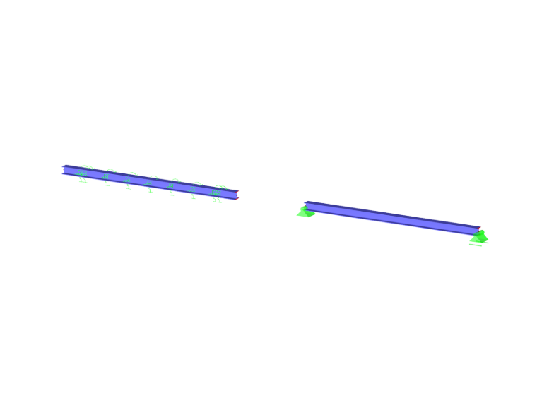
A member support describes the boundary conditions of all FE nodes along a member. The displacements and rotations at these internal nodes can be prevented or restricted by translational and rotational springs. This makes it possible, for example, to model foundation beams as elastic member supports in the model.
Basic
The Basic tab manages the elementary support parameters.
Support conditions
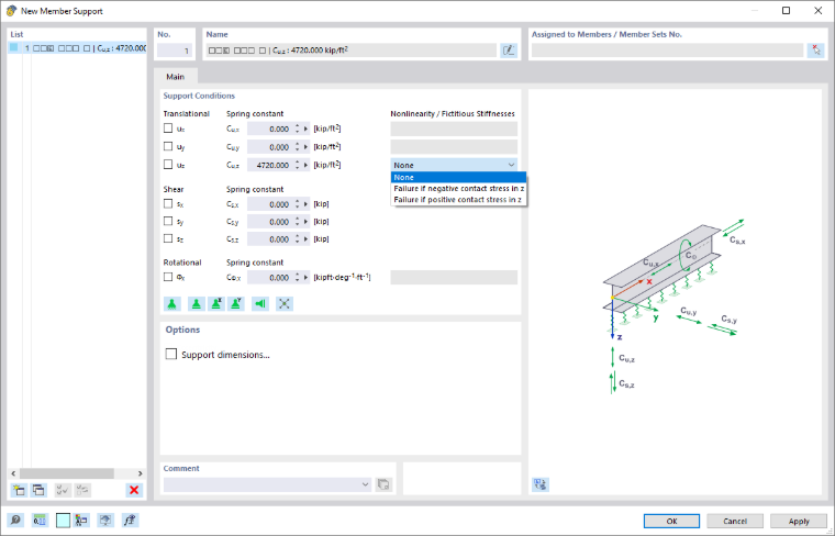
The support conditions are divided into the degrees of freedom 'Translational', 'Shear', and 'Rotational'. To define a support or restraint, check the check box for the respective axis. The check mark symbolizes that the degree of freedom is locked and that the displacement or rotation of the member in or about the respective direction is not possible.
If there is no support or restraint, remove the check mark from the corresponding check box. The constant of the translational or rotational spring is then set to zero. You can adjust the 'Spring constant' at any time to model an elastic support of the member. Enter the spring stiffnesses as design values.
Translational
The 'Spring constant' of a foundation beam must be determined taking into account the cross-section width in order to obtain a member-related translational spring in [N/m2] based on the subgrade reaction. This describes which axial force in [N] per meter of member length and width is required to compress the soil by one meter. Multiply this value by the actual cross-section width and enter the result as spring constant Cu,z (for strip foundations with members in a horizontal position, the local axis z usually points downwards).
For a horizontal or inclined member, the support symbols are always displayed below the member (that is, on the side in the direction of gravity). For a vertical member, the orientation of the member axis z is decisive. A failure, on the other hand, acts independently of the graphical representation: Here, the stress criterion decides, which refers to the orientation of the local z-axis.
For the direction uz, it is possible to define a 'Nonlinearity' (see image New Member Support). The criterion 'Failure if contact stress in z is negative or positive' controls which forces the support can absorb.
For certain add-ons, the nonlinearities 'Shear panel in y' and 'Shear panel in z' are also available.
Check the orientation of the local z-axes if you apply a failure criterion. You can display and hide the member axes using the member shortcut menu.
If the support fails in the direction of the z-axis, the supports in the remaining directions are also ineffective.
Shear
Shear springs can be used to model the shear resistance of the subsoil. The shear stiffness sx describes the axial stiffness due to the axial stiffness E ⋅ A. The spring constants sy and sz are determined as the product of the Poisson's ratio of the soil and Cu,z.
Rotational
The constant of the rotational spring describes how the rotation of the member about its longitudinal axis is restrained. For certain add-ons, the nonlinearity 'Rotational restraint about x' is available.
Options
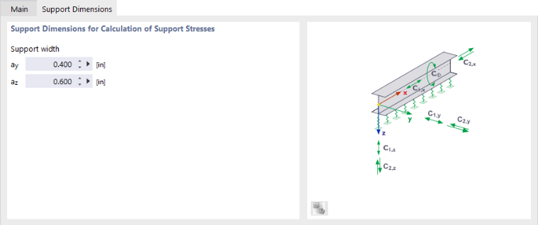
The 'Support dimensions' check box is accessible as soon as a support in the direction of the member axes y or z is present. In the Support dimensions tab, you can then define the geometry of the member support.
Support dimensions
The dimensions of the support are required for determining the support stresses (in preparation).