The structure transfers its loads via the supports into the foundations. Without support, all nodes would be free and unrestricted in their displacements and rotations. If a node is to act as a support, at least one of the degrees of freedom must be locked or restricted by a spring. In addition, the node must be part of a surface or a member.
Imposed deformations of a node are only possible for nodes that are supported accordingly.
If you want to assign nonlinear properties to a nodal support, you can define failure criteria for tensile or compressive forces, cracking and yielding, or working and stiffness diagrams.
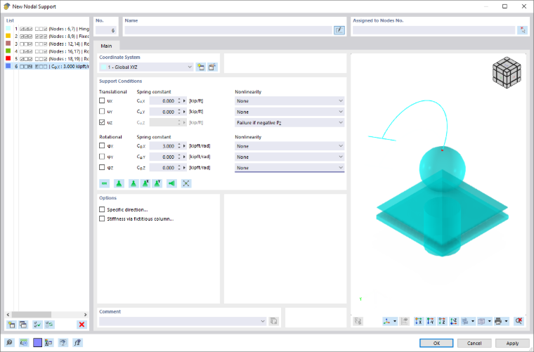
The name symbol of a user-defined nodal support identifies the supported degrees of freedom. The following support types are predefined:
- Hinged
- Rigid
- Movable
- Movable in X'
- Movable in Y'
Basis
The Basis tab manages the elementary support parameters.
Coordinate system
Every nodal support has a local coordinate system. By default, it is aligned parallel to the global X, Y, and Z axes. If you have created a user-defined coordinate system or define it using the
 button, you can also use this reference system.
Support conditions
The support conditions are divided into 'Translational' and 'Rotational' degrees of freedom. The former describe the supports in the direction of the support axes, the latter the restraints about these axes.
To define a support or restraint, activate the check box for the respective axis. The check mark indicates that the degree of freedom is locked and that the displacement or rotation of the node in or about the corresponding direction is not possible.
If there is no support or restraint, remove the check mark from the corresponding check box. The constant of the translational or rotational spring is then set to zero. You can adjust the 'Spring constant' at any time to model an elastic support of the node. Enter the spring stiffnesses as design values.
In the Nonlinearity column, you can specifically control the transfer of the internal forces for each component. Depending on the degree of freedom, suitable entries are available for selection in the nonlinearity list.
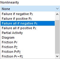
Nominally acting supports are displayed in a different color in the graphic.
Failure if support force/moment negative or positive
This allows you to easily control whether the support can only absorb positive or negative forces or moments: If a force or moment acts in the prohibited direction, this component of the support fails. The remaining restraints and restraints remain effective.
The directions 'negative' and 'positive' refer to the forces or moments that are introduced into the nodal support with respect to the respective axes (that is, not the reaction forces from the support). The signs result from the direction of the global axes: For example, if the global Z-axis is directed downwards, the load case "Self-weight" results in a positive support force PZ.
Failure of all if support force/moment negative or positive
In contrast to the failure of a single component described above, the support fails completely as soon as the component is ineffective.
If you select a different nonlinearity, you can define the parameters in the Partial Activity, Diagram, or Friction tabs.
Options
Using the check boxes in this section, you can define further properties of the nodal support. Depending on the selection, the Specific Direction or Stiffness by Means of Fictitious Column tabs are added. If the 'Concrete Design' add-on is activated, another check box is available for defining the Support Dimensions.
Specific Direction
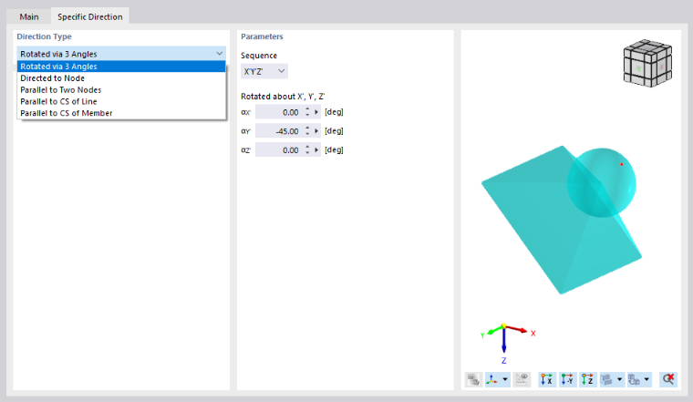
The Specific Direction tab allows you to rotate the support. This means you do not need to create a user-defined coordinate system.
Direction Type
Several options are available for the orientation of the support: You can rotate the support about the support axes X', Y', and Z', align it to one or two nodes, or arrange it parallel to a member or a line. You can select the objects graphically using the
 button.
Stiffness by Means of Fictitious Column
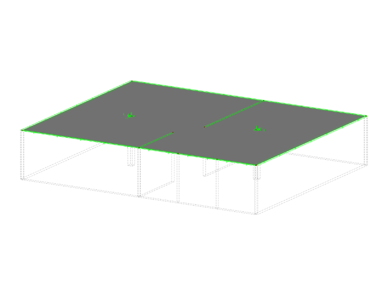
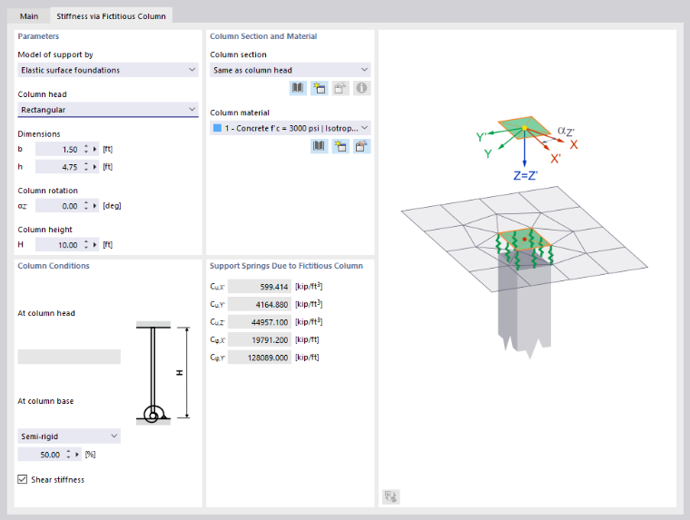
The Stiffness by Means of Fictitious Column tab is particularly recommended for point supports of 2D structures. Here, you can determine the support spring constants from the parameters of a column that is not modeled in the structure. Furthermore, since a point support only rudimentarily represents the conditions in the column head area, special column macro-elements are available. From the boundary conditions, RFEM determines the spring stiffnesses of the support. This enables a realistic modeling without the singularity effects that would result from a rigid support in a single FE node.
Parameters
Three approaches are available for the 'Support model'. Each is symbolized in the dialog graphic.
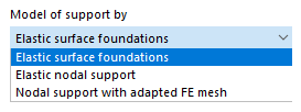
- In the 'Surface foundation' model, a surface is detached in the column dimensions and elastically founded. The subgrade reaction moduli are determined from the geometry and material data of the column.
- In the 'Elastic nodal support' model, a surface is detached and supported at a point. The support is provided with translational and rotational springs that result from the geometry and material data of the column. To take into account the higher bending stiffness in the column area, the surface is doubled internally.
- The 'Nodal support with adapted FE mesh' model corresponds to the elastic nodal support, but no springs are applied at the point supports.
Enter the data for the column that is required for determining the spring stiffnesses. The 'Column head' geometry can be described as rectangular or circular, optionally with a rotation of the column.
The 'Column height' affects the constants of the translational and rotational springs.
Column Cross-section and Material
The cross-section and material properties of the column are required for determining the spring stiffnesses. If the column is not 'Identical to the column head' (that is, neither rectangular nor circular), you can select or newly define a suitable column cross-section in the list.
Select the 'Column material' from the list. Using the
 and
buttons, you can create a new material.
and
buttons, you can create a new material.
Column Conditions
The type of support at the column head and column base is included in the determination of the translational and rotational springs. The following options are available in the list:
- Hinged
- Flexible
- Rigid
For the 'Flexible' option, you can specify the degree of restraint at the column base in percent.
The 'Shear stiffness' of the column is taken into account by default when determining the stiffnesses.
Support Springs Due to Fictitious Column
This section lists the constants of the support springs that result from the geometry and material properties of the column. The values are transferred to the 'Basis' tab.
Support Dimensions
The dimensions of the support are required for determining the loaded area for the punching shear design. This tab is therefore only accessible if the Concrete Design add-on is activated.
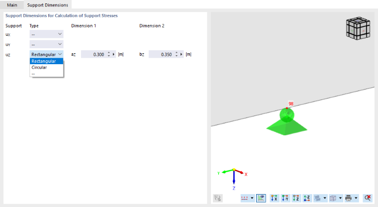
For each component of the translational support, define the 'Type' that describes the shape of the storage space – rectangular or circular. You can then define the geometry of the support in the other columns using the lengths or the diameter.
Partial Activity
The Partial Activity of a support component is available as a nonlinear property of the support (see image Selecting Support Nonlinearity).
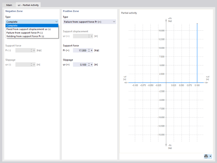
Define the activity of the support for the 'Negative range' and the 'Positive range'. The sign convention is explained in the Failure section. Various criteria for the effectiveness of the support are available in the 'Type' list.
- Full: The support component is fully effective.
- Fixed from support displacement/support rotation: The stiffness of the translational or rotational spring is only effective up to a certain displacement or rotation. If this is exceeded, a fixed support or restraint becomes effective.
- Cracking from support force/support moment: The support is only effective up to a certain force or moment. If this is exceeded, the support fails.
- Yielding from support force/support moment: The support is only effective up to a certain force or moment. If this is exceeded, the strains increase, but no longer the stresses.
- Failure: The support component is ineffective.
Most support types can be combined with a 'slippage', whereby the support only becomes effective after a certain displacement or rotation.
Diagram
The Diagram of a support component is available as a nonlinear property of the support (see image Selecting Support Nonlinearity).
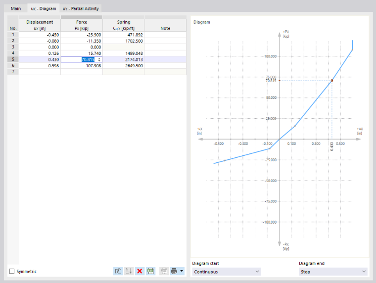
In the 'Displacement' or 'Rotation' column, define the number of definition points of the working diagram with the corresponding values. In the 'Force' or 'Moment' column, you can then assign the abscissa values of the displacements or rotations to the support forces or moments.
Using the
 button, you can import the diagram from an Excel spreadsheet. If the order of the definition points is incorrect, you can sort the entries in ascending order using the
 button.
The following criteria are available for the 'Diagram start' and 'Diagram end':
- Cracking: The support is only effective up to the maximum value of the force or moment. If this is exceeded, the support fails.
- Yielding: The support is only effective up to the maximum value of the force or moment. If this is exceeded, the strains increase, but no longer the stresses.
- Continuous: Beyond the definition range, the spring constant of the last step is applied.
- Stop: The permissible deformation is limited to the maximum value of the displacement or rotation. If this is exceeded, a fixed support or restraint becomes effective.
Stiffness Diagram
The Stiffness diagram of a support component is available as a nonlinear property of a rotational support.
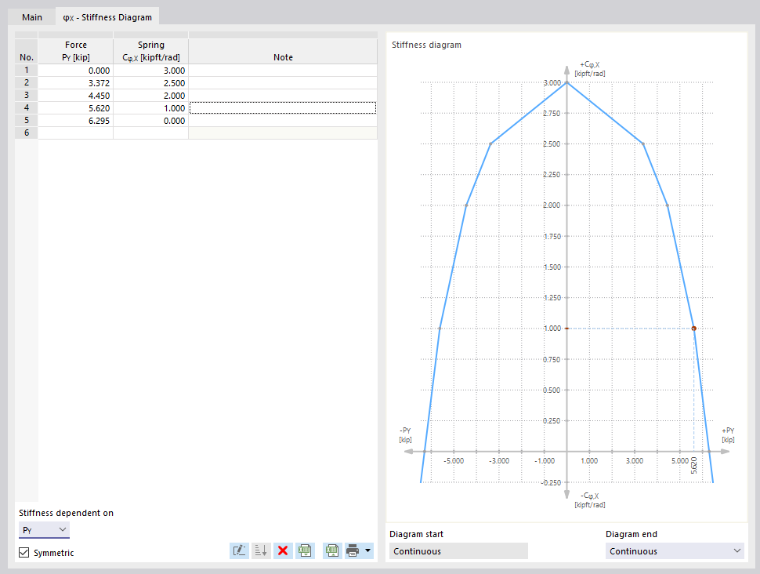
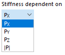
First, in the 'Stiffness depending on' list (at the bottom of the tab), define the component of the support force on which the spring stiffness depends. The option |P| represents the resulting support force.
Then, in the 'Force' column, define the number of definition points of the working diagram with the corresponding characteristic values. In the 'Spring' column, you can then assign the respective spring constants.
The following criteria are available for the 'Diagram start' and 'Diagram end':
- Cracking: The support is only effective up to the maximum value of the force. If this is exceeded, the support fails.
- Yielding: The support is only effective up to the maximum value of the force. If this is exceeded, the strains increase, but no longer the stresses.
- Continuous: Beyond the definition range, the spring constant of the last step is applied.
Friction
In the 'Nonlinearity' list, four options are available for defining the friction of the translational support depending on another support component (see image Selecting Support Nonlinearity).
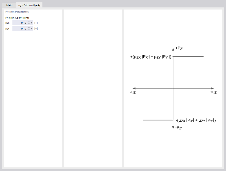
The transferred support forces are set in relation to the compressive forces acting in another direction. Depending on the selection in the 'Basis' tab, the friction depends on only one support force or on the total force of two simultaneously acting support forces. The following relationship exists between the support force and the friction force:
The FAQ 003537 explains how friction can be taken into account at a nodal support.
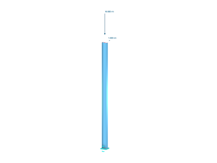
The following column model shows a support in which horizontal forces are transferred by friction. However, the horizontal forces may be at most 10% of the vertical force. In LC 1, this condition is met. In LC 2, the model becomes unstable because the horizontal load is too large.
Scaffolding Hinge
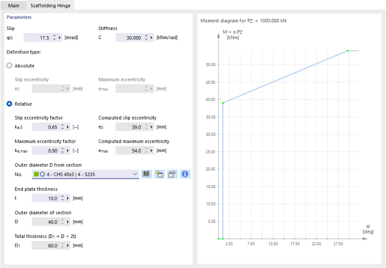
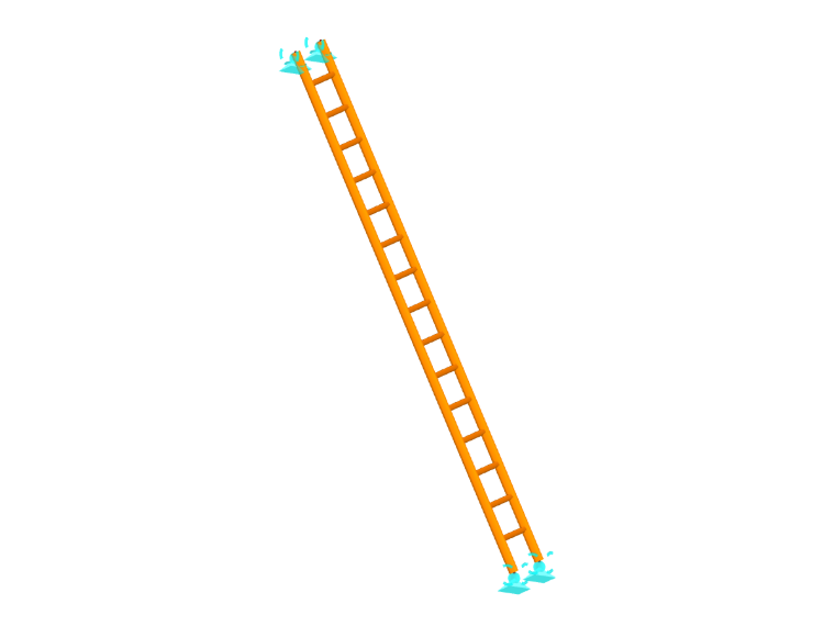
The Scaffolding hinge is available as a nonlinear property of the support for the rotational degrees of freedom φX and φY. This allows you to define scaffolding supports for temporary structures such as working scaffolds or props.
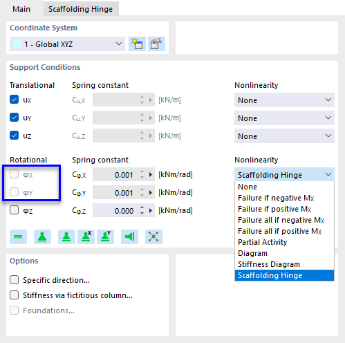
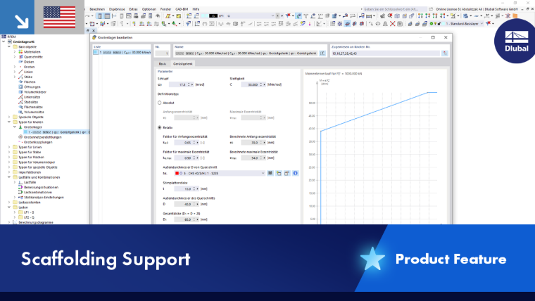
In the 'Scaffolding Hinge' tab, you can define the M-φ working diagram. The parameters are described in more detail in the product feature Scaffolding Support.