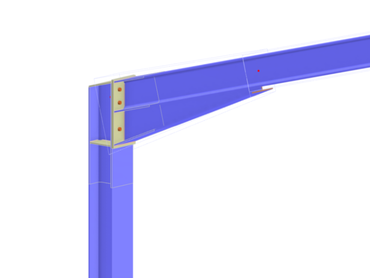
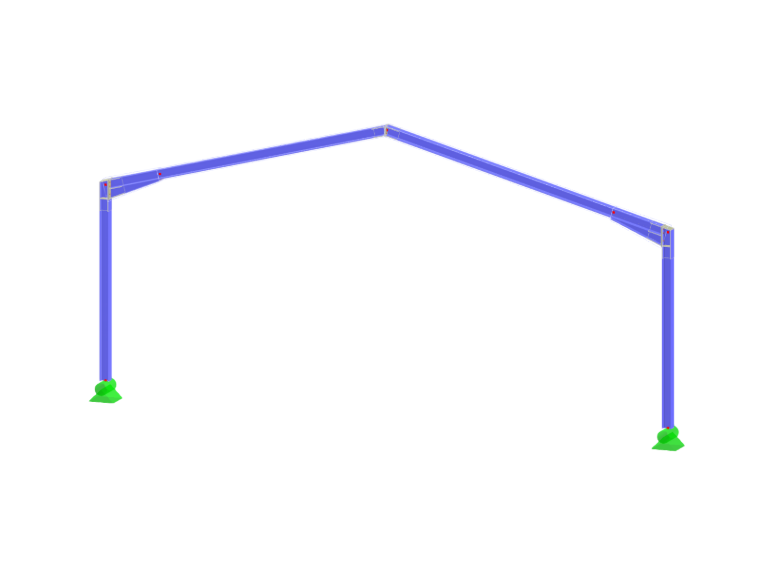
Yes, this is easily possible.
Modeling Tapered Beam
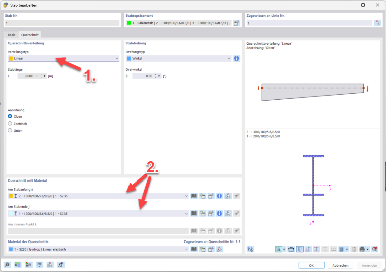
To create a tapered beam, select the Linear distribution type, for example, in the Sections tab of the Edit Member dialog box. This allows you to assign different cross-sections to the member start and end.
Prerequisite: Interpolability of Cross-Sections
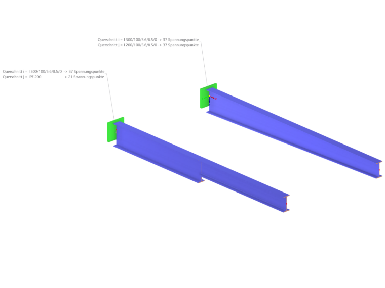
To ensure that RFEM can correctly calculate the distribution between the cross-sections, they have to be interpolable. This is the case under the following conditions:
- Number and location of stress points: The cross-sections should have the same number of stress points, and their relative locations should correspond.
- Angle tolerance: The maximum angle difference between the cross-section segments should not exceed 0.1 rad (approx. 5.73°).
Recommended Modeling with RSECTION
Parametric cross-sections created in RSECTION 1 can always be interpolated, which is why the following procedure is recommended:
- 1. Create a parametric cross-section in RSECTION.
- 2. Import the cross-section into RFEM 6.
- 3. Create a variant: Save the cross-section with different parameters (for example, a larger web height for the taper).
- 4. Assignment: Use these two variants as the initial and final cross-sections for the tapered beam.
You can also find detailed instructions on this in the webinar:
Modeling of Parametric Cross-Sections in RSECTION 1 and Use in RFEM 6
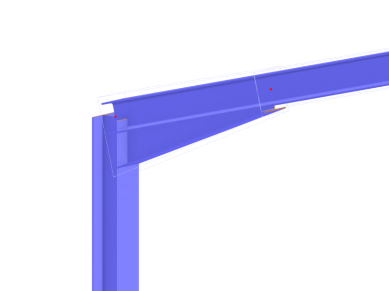
With this modeling method, it is also possible to model real-world tapered beams like this one:
Design
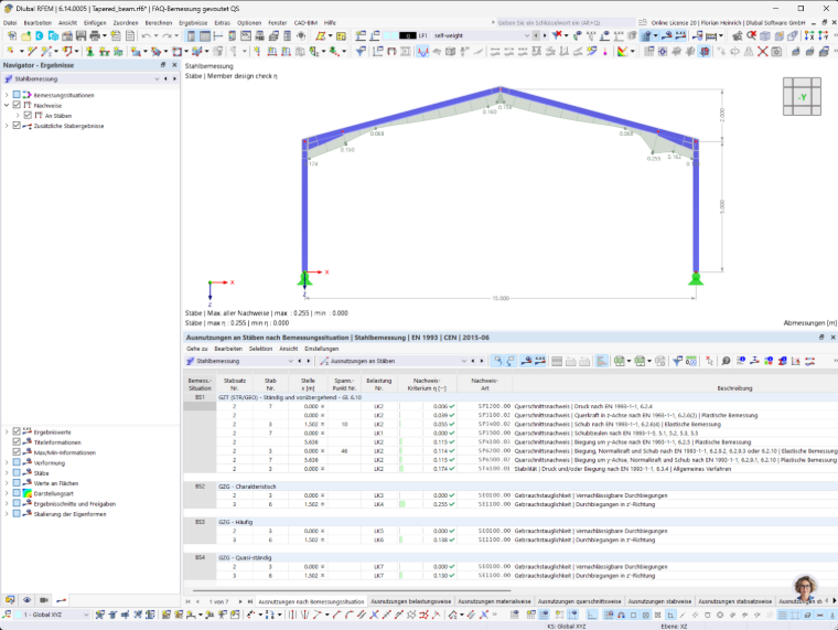
After modeling, the tapered beam can be designed using the Steel Design add-on.
Stability Analysis According to Eurocode 3
For tapered structural components, the following methods are available according to EN 1993-1-1:
- General Method according to Section 6.3.4.
- Equivalent Imperfection Method (taking into account second-order analysis and warping torsion).
Additional Joint Design
Furthermore, you can use the Steel Joints add-on to realistically model and perform structural design for the transition from a tapered beam to a column.
Printout Report for FAQ 005805: Modeling and Design of Tapered Beams