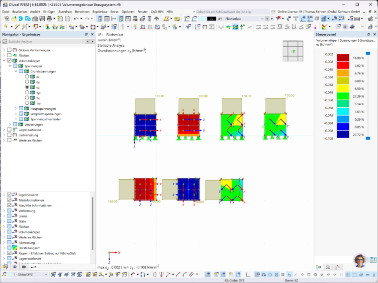
When creating a new solid, the global coordinate system is used by default as both the geometric coordinate system for the solid and the calculation coordinate system for the results.
To deviate from the default setting, you can use the “Specific Direction...” option:
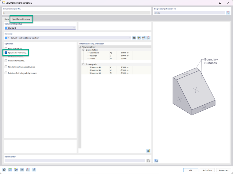
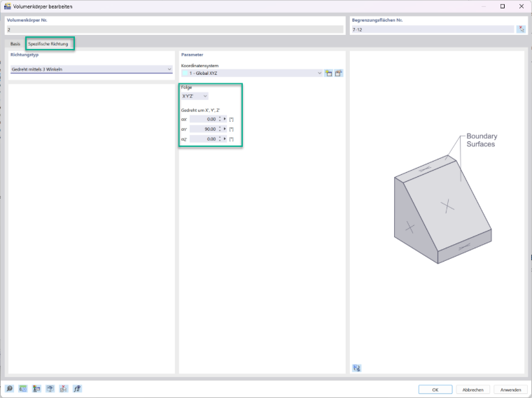
By activating this option, you gain access to the corresponding new tab. The settings within this tab affect the geometric coordinate system of the solid and, at the same time, the coordinate system to which the calculation results—for example, the residual stresses—are related:
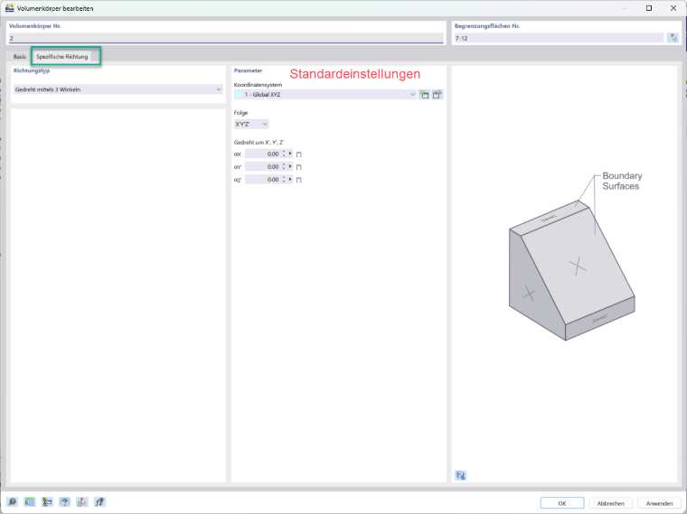
Here, you have the option to switch the coordinate system of the solid to a user-defined coordinate system:
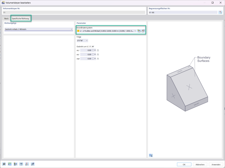
If you subsequently disable the “Specific Direction...” option, the last selected coordinate system for the solid remains in use.
You also have the option to further rotate the reference system of the solid.
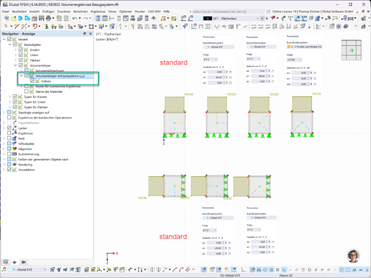
The following image shows the coordinate systems of the solid models with different settings for the specific directions:
The following images show the coordinate systems of the individual finite elements of the solid models:
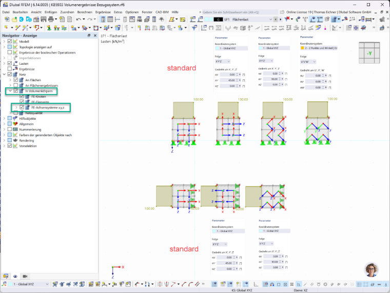
Finally, we can analyze the results for the basic stresses in the z-direction. As shown in the image, these refer to the z-axis of the finite elements: