2026-09-17
064975
Tension Stiffening | Activation Factor: Capacity, Angle, and Position
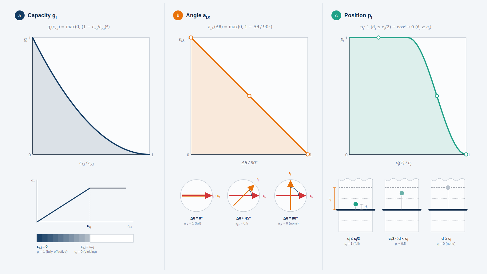
Diagrams of the three partial factors of the activation factor, capacity, angle, and position, of the local anisotropic tension-stiffening augmentation
Three-part graphic showing the multiplicative partial factors of the activation factor Δα_j,k. Part a shows the capacity factor g_j as a quadratically decreasing curve from 1 to 0 over the ratio of reinforcement strain to yield strain, supplemented by the associated stress-strain curve of the reinforcement. Part b shows the angle factor a_j,k as a straight line decreasing linearly from 1 to 0 over the angle between the reinforcement direction and the principal tension direction, referenced to 90 degrees, with three example sketches for 0, 45, and 90 degrees. Part c shows the position factor p_j as a curve with a cosine-squared transition, fully effective within half the concrete cover, decreasing up to the full concrete cover, and zero beyond that, with three cross-section sketches as an explanation.