2026-06-10
063115
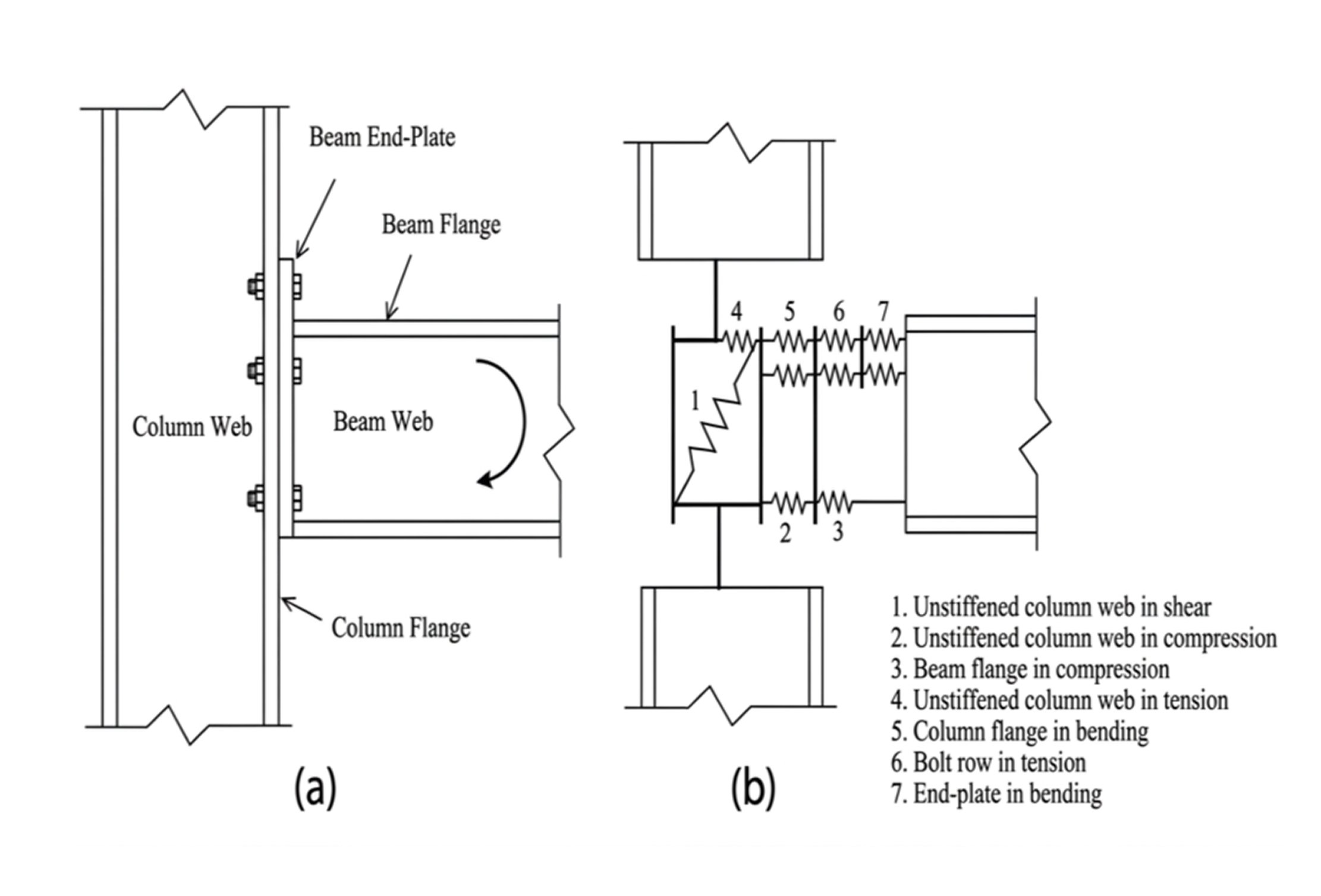
(a) Typical Beam-Column Bolted Connection and (b) Component Method Representation
Schematic diagram of a bolted beam-column connection and its mechanical model using the component method for structural steel design.
The illustration presents the component method for modeling a bolted beam-to-column connection. Part (a) shows the physical configuration of an extended end-plate connection identifying the column web, column flange, beam web, beam flange, and beam end-plate. Part (b) displays the equivalent mechanical model consisting of seven individual components.